Internet of Things video monitoring system with automatic camera cleaning function

A video surveillance system and automatic cleaning technology, which is applied to closed-circuit television systems, components of television systems, televisions, etc., can solve the problems of inconvenience of manual cleaning and affect the effect of video surveillance, and achieve good cleaning effect, simple structure, and easy cleaning. good effect

Inactive Publication Date: 2015-01-14
嘉兴市新飞腾塑业有限公司
View PDF10 Cites 8 Cited by
  • Summary
  • Abstract
  • Description
  • Claims
  • Application Information

AI Technical Summary

Problems solved by technology

[0003] One of the most important components in video surveillance is the camera, but the cameras in the currently installed video surveillance are exposed to the air, whether it is an indoor camera or an outdoor camera, after a long time, the mirror surface of the camera It will be stained with dust, which will affect the monitoring effect of the video, and the camera is basically installed at a certain height, so manual cleaning is inconvenient

Method used


Image

  • Internet of Things video monitoring system with automatic camera cleaning function
  • Internet of Things video monitoring system with automatic camera cleaning function
  • Internet of Things video monitoring system with automatic camera cleaning function

Examples


Embodiment 1

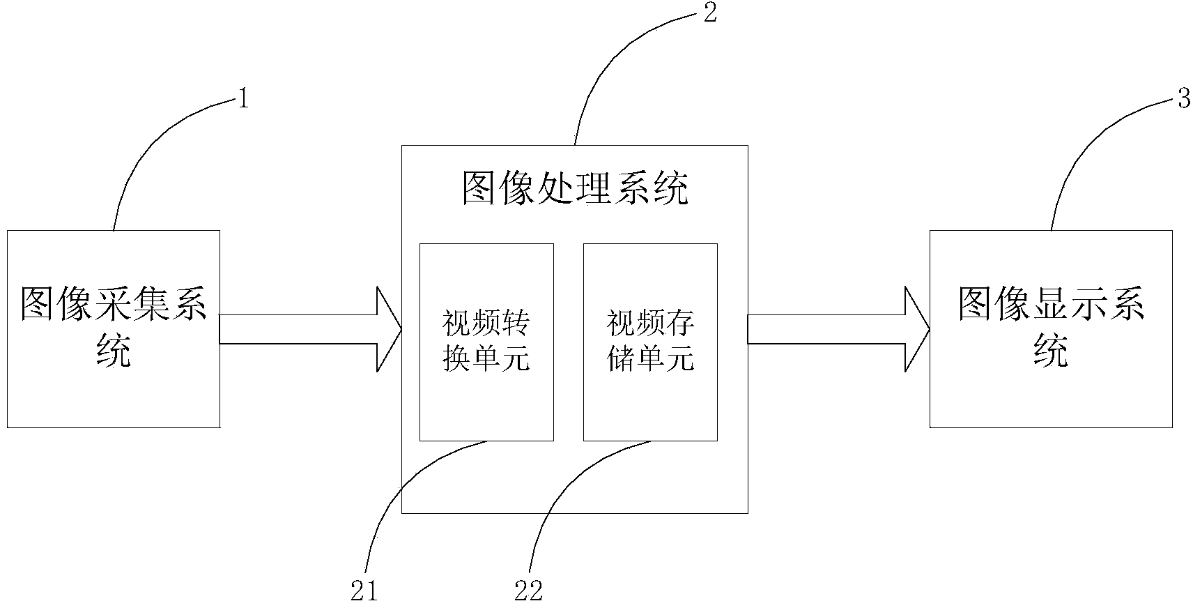
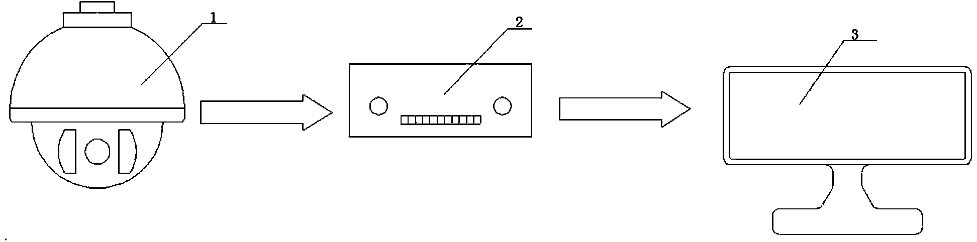
[0039] Embodiment 1, the Internet of Things video monitoring system as described above, the difference of this embodiment is that, as figure 2 As shown in the system diagram of the Internet of Things video monitoring system of the present invention; the image acquisition subsystem 1 is a camera 1; the image processing subsystem 2 is an image converter 2; the image display subsystem 3 is A large-screen display 3; the camera 1 is used to monitor the real-time picture, and the image converter 2 is used to accept the real-time picture and perform conversion processing; the image display subsystem 3 accepts the processed The video screen is displayed.

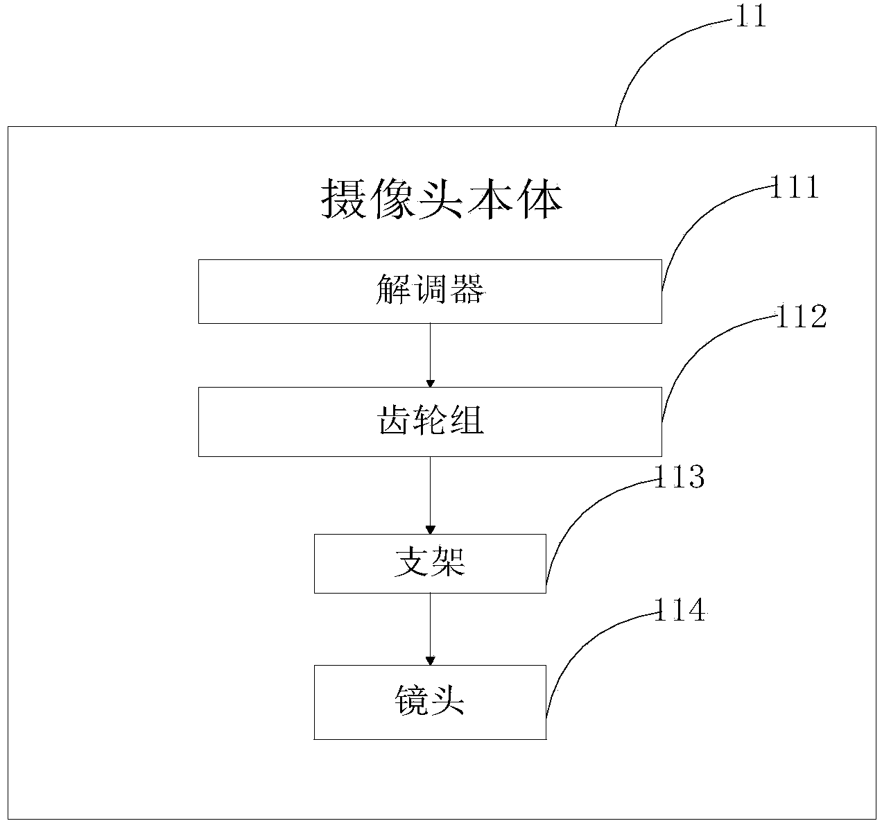
[0040] See how image 3 As shown, it is a functional block diagram of the camera of the present invention; the camera body 11 includes a demodulator 111, a gear set 112, a bracket 113, and a lens 114, and the demodulator 111 is used to control the The lens 114 rotates, and supplies power to the camera body 11; the gear set 112 is...

Embodiment 2

[0042] Embodiment 2, as the above-mentioned camera in the prior art, the difference of this embodiment is that, as Figure 4As shown in the structure diagram of the camera of the present invention, the camera 1 includes the camera body 11 including a demodulator 111, a gear set 112, a bracket 113, a lens 114, a camera cover 115, and a camera mirror 116 , the camera housing 115 is nested with the camera mirror 116, the demodulator 111 and the gear set 112 are installed inside the camera housing 115, and the regulator 111 and the The gear set 112 is connected by a first transmission shaft; the camera lens 116 is internally installed with the bracket 113 and the lens 114, the lens 114 is installed on the bracket 113, and the bracket 113 is connected to the bracket 113 The gear sets 112 are connected through the second transmission shaft; when the camera 1 is working, the demodulator 111 is powered, and the transmission shaft drives the gear shaft 112 to rotate, and the transmissi...

Embodiment 3

[0044] Embodiment 3, as the functional block diagram of the camera in the prior art described above, the difference of this embodiment is that a cleaning device is added, such as Image 6 Shown in the structural diagram of the camera head with automatic cleaning function of the present invention, it is the structural diagram of the camera head with automatic cleaning function of the present invention; Described camera head 1 comprises a cleaning device 117, and described cleaning device 117 is installed in described The lower end of the camera housing 115; the cleaning device 117 includes a rotary connector 1171 and a cleaning panel 1172, the rotary connector 1171 and the cleaning panel 1171 are linked by a rotating shaft, when the camera 1 works At this time, the adjuster 111 drives the lens 114 to rotate in a circle, and through the gear set, drives the cleaning device 117 to rotate in a circle together to clean the surface of the camera mirror 116 .

[0045] The camera of t...


PUM


Abstract

The invention provides an Internet of Things video monitoring system with the automatic camera cleaning function. The Internet of Things video monitoring system comprises an image collecting subsystem, an image processing subsystem and an image displaying subsystem. The image processing subsystem comprises a video converting unit and a video storing unit, and the video converting unit is used for carrying out format conversion on images of a monitoring picture. The video storing unit is used for storing the images with the processed format. The image collecting subsystem is a camera, the camera comprises a camera body and a cleaning device, and the camera body is used for monitoring real-time pictures. The cleaning device is used for cleaning dust and small particles on the surface of the camera body. The cleaning device not only can clean the dust on the mirror surface of the camera, but also can reduce light reflection and refraction, and the video pictures can be clearer.

Description

technical field [0001] The invention relates to an Internet of Things video monitoring system, in particular to an Internet of Things video monitoring system with an automatic cleaning camera. Background technique [0002] With the development of science and technology, the field of application of video surveillance is more and more extensive. In terms of traffic video monitoring, it can monitor the violations of vehicles and play the images in real time, making road traffic more orderly; in terms of hospital monitoring, it can monitor the physical condition of patients in real time. In terms of biological research, it can also observe the growth status of plants. [0003] One of the most important components in video surveillance is the camera, but the cameras in the currently installed video surveillance are exposed to the air, whether it is an indoor camera or an outdoor camera, after a long time, the mirror surface of the camera It will be stained with dust, which will...

Claims


Application Information

Patent Timeline
Patent Type & Authority Applications(China)
IPC IPC(8): H04N7/18H04N5/225
Inventor 张乾王辉
Owner 嘉兴市新飞腾塑业有限公司
Why Eureka
Try Eureka