Eccentric clamping fixture

An eccentric clamping and fixture technology, applied in the direction of clamping, manufacturing tools, support, etc., can solve the problem that the clamping jaw cannot guarantee the clamping accuracy, etc., and achieve the effect of convenient modification, tight fit and simple clamping structure.

Inactive Publication Date: 2015-01-21
CHONGQING HAONENG XINGFU SYNCHRONIZER
View PDF0 Cites 5 Cited by
  • Summary
  • Abstract
  • Description
  • Claims
  • Application Information

AI Technical Summary

Problems solved by technology

[0003] In the existing fixtures, the threaded rod is equipped with two sections of threads with opposite rotations as the transmission mechanism for driving the jaws. It is a common structure for quickly clamping the workpiece. Most of this type of fixtures are not equipped with locking devices. Instead, the self-locking feature of this type of fixture is used to lock, but the problem now is that the jaws of this type of fixture cannot guarantee the clamping accuracy when the force is increased.

Method used


Image

  • Eccentric clamping fixture

Examples


Embodiment Construction

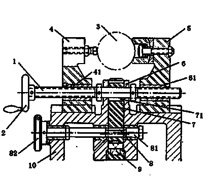
[0016] combined with figure 1 The shown eccentric clamping fixture includes a base 10 and a threaded column 1, wherein the end of the threaded column 1 is fixedly connected with a hand wheel 2, and left and right external thread sections of the same length are provided at both left and right ends of the threaded column 1 41 and right threaded section 42, threaded column 1 middle part has a section of blank section, left external threaded section 41 and right threaded section 42 have the opposite direction of thread rotation, left external threaded section 41 and right threaded section 42 are evenly connected with splints, left The splint 4, and the middle part of the right splint 5 are all provided with through holes, and the left threaded sleeve 41 and the right threaded sleeve 51 of the opposite direction of rotation are welded in the two through holes, and the left splint 4 and the right splint 5 are all connected to the base 10 The other end of the sliding connection is a ...


PUM


Abstract

The invention relates to a machining fixture, in particular to an eccentric clamping fixture. The eccentric clamping fixture comprises a base and a threaded column, a hand wheel is fixedly connected at the end of the threaded column, the threaded column is divided into a left part and a right part, each of the two parts is provided with a thread, two sections of the threads are opposite in thread turning direction, each of the left part and the right part is in threaded connection with a clamping plate, ends of the clamping plates are slidably connected with the base while the other ends are used for clamping workpieces, a boss is arranged on the base and between two clamping jaws, the clamping jaws are slidably connected in the boss, a through hole is formed in a drive end of each clamping jaw, a cam matched with the corresponding through hole and capable of locking the corresponding clamping jaw is arranged in the through hole, and the each cam is provided with a handle; the threaded column penetrates driven ends of the clamping jaws, and clamping holes for penetrating of the threaded column are formed in the driven ends of the clamping jaws. By the machining fixture, machining precision under the condition that reacting force in clamping of the workpieces is guaranteed.

Description

technical field [0001] The invention relates to a machine tool fixture, in particular to an eccentric clamping fixture. Background technique [0002] The device used to fix the processing object in the process of mechanical manufacturing so that it occupies the correct position to accept construction or inspection, also known as fixture. In a broad sense, any process in the process, the device used to install the workpiece quickly, conveniently and safely, can be called a fixture. Such as welding fixtures, inspection fixtures, assembly fixtures, machine tool fixtures, etc. Among them, machine tool fixtures are the most common, often referred to as fixtures. When processing a workpiece on a machine tool, in order to make the surface of the workpiece meet the technical requirements such as the size, geometric shape, and position accuracy with other surfaces specified in the drawing, the workpiece must be installed (positioned) and clamped (clamped) before processing. . The...

Claims


Application Information

Patent Timeline
Patent Type & Authority Applications(China)
IPC IPC(8): B23Q3/00
CPCB23Q3/00
Inventor 张敏
Owner CHONGQING HAONENG XINGFU SYNCHRONIZER
Why Eureka
Try Eureka