Laser fuse reception system

A receiving system and laser fuze technology, applied in the field of laser fuze, can solve the problems of photoelectric crosstalk, long action distance, large field of view of laser fuze, etc., reduce thermal noise and shot noise, improve receiving efficiency, increase filtering and distance Effect of Gain Control Function

Inactive Publication Date: 2015-01-21
SHANGHAI RADIO EQUIP RES INST
View PDF3 Cites 13 Cited by
  • Summary
  • Abstract
  • Description
  • Claims
  • Application Information

AI Technical Summary

Problems solved by technology

[0004] The purpose of the present invention is to provide a laser fuze receiving system, which solves the problem of photoelectric crosstalk by setting a photodetector and a preamplifier circuit in the receiving system; at the same time, a distance gain control circuit is set to increase the signal filtering and distance gain functions, Solve the problem of large field of view and long working distance of laser fuze, and improve the receiving rate

Method used


Image

  • Laser fuse reception system
  • Laser fuse reception system
  • Laser fuse reception system

Examples


Embodiment Construction

[0040] The present invention will be further elaborated below by describing a preferred specific embodiment in detail in conjunction with the accompanying drawings.

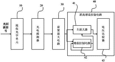
[0041] Such as figure 1 As shown, a laser fuze receiving system includes: a receiving optical unit 10 , a photodetector 20 , a preamplifier circuit 30 and a distance gain control circuit 40 .

[0042] The photodetector 20 is connected to the receiving optical unit 10 ; the preamplifier circuit 30 is connected to the photodetector 20 ; the input end of the distance gain control circuit 40 is connected to the output end of the preamplifier circuit 30 .

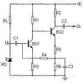
[0043] When the requirement on the input impedance of the preamplifier circuit 30 is not high and the volume size permits, an ordinary low-noise triode can be used as the preamplifier circuit, and its bandwidth requirement and noise can meet the requirements. In this application, two-stage common-emitter transistors are used to design the preamplifier circuit 30 ....


PUM


Abstract

The invention discloses a laser fuse reception system, which comprises a reception optical unit, a photoelectric detector connected to the reception optical unit, a preposition amplification circuit connected to the photoelectric detector, and a distance gain control circuit connected to an output terminal of the preposition amplification circuit. According to the invention, the photoelectric detector and the preposition amplification circuit arranged in the reception system, a photoelectric crosstalk problem can be solved; the distance gain control circuit is arranged, so that signal filtering and distance gaining functions can be increased, problems of large laser fuse view field and long effect distance can be solved, and reception rate is increased.

Description

technical field [0001] The invention relates to the field of laser fuzes, in particular to a laser fuze receiving system. Background technique [0002] The receiving system of the laser fuze needs to convert the received optical signal into an electrical signal, and then send it to the subsequent circuit after amplification and shaping. [0003] There are many domestic units researching laser fuzes. But it is basically limited to algorithm research and modeling, and it is the research on larger targets such as ships and helicopters, while the research on laser fuzes for low-altitude and small targets is almost blank. For large and small targets at ultra-low altitudes, the projectile-eye intersection is complicated. In order not to miss the target, the laser fuze must be able to detect the target within the 360° range of the projectile axis. At present, domestic receiving systems use avalanche photodiodes (APD), photomultiplier tubes and PIN silicon detection systems, but t...

Claims


Application Information

Patent Timeline
Patent Type & Authority Applications(China)
IPC IPC(8): F42C13/02H03F1/26
Inventor 朱晓蕾
Owner SHANGHAI RADIO EQUIP RES INST
Why Eureka
Try Eureka