
An in situ xrd reaction chamber for testing the electrochemical reaction process

An electrochemical reaction and reaction chamber technology, which can be applied to measurement devices, scientific instruments, instruments, etc., can solve the problems of inconvenient maintenance, high price, complex structure, etc., and achieve the effect of easy assembly and disassembly, and simple structure.

Active Publication Date: 2017-01-11
GUANGXI NORMAL UNIV
View PDF4 Cites 0 Cited by
  • Summary
  • Abstract
  • Description
  • Claims
  • Application Information

AI Technical Summary

Problems solved by technology

[0005] For the in-situ XRD reaction chamber, the currently commercialized one is the XRK900 reaction chamber of Anton Paar Company in Austria. It is a reaction chamber specially designed for in-situ X-ray diffraction experiments, but it is expensive and inconvenient to maintain. What is more interesting is that the appearance of different reaction systems is quite different. For example, in the in-situ XRD test of battery materials during charging and discharging, there is the extraction of battery current collectors. When studying the catalytic principle of catalysts under different atmospheres, there must be atmosphere ventilation. In and out, the existing in-situ reaction chamber is difficult to meet the above-mentioned in-situ XRD test requirements for these systems
At present, some in-situ XRD reaction chambers have been designed at home and abroad, especially for electrochemical on-site analysis, but their structures are too complicated, and these in-situ XRD reaction chambers are limited to in-situ XRD electrochemical reaction chambers. , the function is relatively simple

Method used


Image

  • An in situ xrd reaction chamber for testing the electrochemical reaction process

Examples


Embodiment Construction

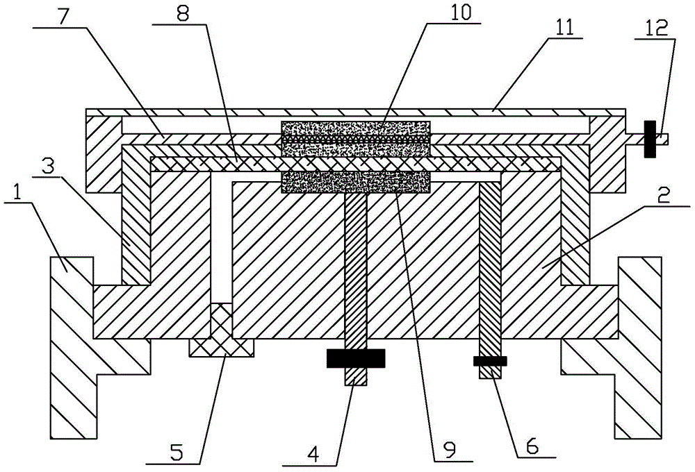
[0024] Such as figure 1 As shown, the in-situ XRD reaction chamber for testing the electrochemical reaction process of the present invention includes a fixed seat 1, a negative electrode seat arranged on the fixed seat 1 and a positive electrode seat 7 arranged above the negative electrode seat, and a positive electrode seat 7 arranged on the positive electrode seat. The test window 11 at the top of the seat 7; wherein:

[0025] The fixed seat 1 is hollow cylindrical, and an annular convex card is arranged on the inner wall surface of the middle and lower part of the fixed seat 1;

[0026] The negative pole seat includes a negative pole base 2 and a negative pole screw cap 3, both of which are threadedly connected, a first through hole is opened in the middle of the negative pole spin cap 3, and a layer of diaphragm is arranged on the top of the inner cavity of the negative pole spin cap 3 8. The top of the diaphragm 8 is in contact with the top of the inner cavity of the scr...


PUM


Abstract

The invention discloses an in-situ XRD reaction chamber for testing an electrochemical reaction process. The in-situ XRD reaction chamber comprises a fixing seat, a negative seat, a positive seat and a test window, wherein the negative seat is arranged on the fixing seat and comprises a negative base and a negative screw cover which are connected in a threaded mode; a first through hole is formed in the negative screw cover; a negative base body is arranged in an inner cavity of the negative screw cover; more than two air holes are formed in the negative base, and a negative lead column is arranged on the negative base; a sealing plug is arranged at the bottom end of each air hole; one end of the negative lead column is in contact with the negative base body, and the other end of the negative lead column extends out of the negative base; the positive seat comprises an annular screw cover, a positive base body arranged on the annular screw cover, and a positive lead column; the positive base body is arranged in a second through hole in the annular screw cover; a gap formed by the negative base and the negative screw cover is filled with an electrolyte; the test window is formed in the top end of the annular screw cover; a clearance is reserved between the bottom end of the test window and the top end of the positive base body. The in-situ XRD reaction chamber is simple in structure and is applicable to a two-electrode system and a three-electrode system.

Description

technical field [0001] The invention relates to an in-situ XRD reaction chamber for testing an electrochemical reaction process, and belongs to the technical field of in-situ XRD testing. Background technique [0002] In-situ XRD (XRD is X-ray diffractometer) testing technology is currently the fastest-growing XRD testing technology. In situ XRD, as the name implies, is to keep the sample immobile and measure the diffraction patterns of the same sample under different conditions (such as temperature, current and voltage, atmosphere, etc.). The advantage of in-situ testing is that it can monitor the changes of the sample when the conditions change in real time, and can truly reflect the actual changes of the system under the given conditions. For the in-situ XRD test, it is possible to truly monitor the change of the internal structure of the sample with the reaction conditions (temperature, current and voltage, atmosphere). After knowing the corresponding relationship betwe...

Claims


Application Information

Patent Timeline
Patent Type & Authority Patents(China)
IPC IPC(8): G01N23/207
Inventor 黄有国昝亚辉李庆余王红强
Owner GUANGXI NORMAL UNIV
Learn More