
Three-dimensional dip angle domain stationary phase pre-stack time migration method and system

A pre-stack time migration and three-dimensional dip technology, applied in the field of seismic exploration, can solve the problem of low signal-to-noise ratio of migration images

Active Publication Date: 2015-01-21
INST OF GEOLOGY & GEOPHYSICS CHINESE ACAD OF SCI
View PDF7 Cites 25 Cited by
  • Summary
  • Abstract
  • Description
  • Claims
  • Application Information

AI Technical Summary

Problems solved by technology

[0006] The technical problem to be solved by the present invention is to provide a three-dimensional dip domain stable phase prestack time migration method and system, which are used to improve the signal-to-noise ratio of migration imaging and solve the problem of existing migration imaging technology when steep dip structures exist. The problem of low signal-to-noise ratio of the offset image

Method used


Image

  • Three-dimensional dip angle domain stationary phase pre-stack time migration method and system
  • Three-dimensional dip angle domain stationary phase pre-stack time migration method and system
  • Three-dimensional dip angle domain stationary phase pre-stack time migration method and system

Examples


Embodiment Construction

[0068] In order to improve the signal-to-noise ratio of migration imaging and solve the problem of low signal-to-noise ratio of migration images obtained by existing migration imaging techniques in the presence of steep dip structures, the present invention provides a three-dimensional dip-domain phase-stabilized prestack time migration The shifting method and system will be further described in detail below in conjunction with the accompanying drawings and embodiments. It should be understood that the specific embodiments described here are only used to explain the present invention, not to limit the present invention.

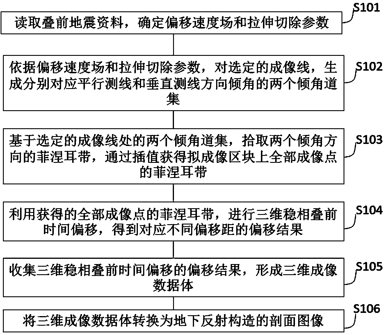
[0069] Such as figure 1 As shown, a three-dimensional dip domain stable phase prestack time migration method in the embodiment of the present invention includes:

[0070] S101, read the pre-stack seismic data, determine the migration velocity field and stretching and cutting parameters;

[0071] S102, according to the migration velocity field and the stretc...


PUM


Abstract

The invention discloses a three-dimensional dip angle domain stationary phase pre-stack time migration method and system. The method comprises the steps that pre-stack seismic data are read, and a migration speed field and a stretching and removing parameter are determined; according to the migration speed field and the stretching and removing parameter, two dip angle channel sets corresponding to dip angles in the directions parallel to and perpendicular to a measuring line respectively are generated through a selected imaging line; based on the two dip angle channel sets on the selected imaging line, Fresnel zones in the two dip angle directions are picked up, and the Fresnel zones of all imaging points on a quasi imaging block are obtained through interpolation; through the obtained Fresnel zones of all the imaging points, three-dimensional stationary phase pre-stack time migration is carried out, and migration results corresponding to different migration distances are obtained; the migration results of three-dimensional stationary phase pre-stack time migration are collected, and a three-dimensional imaging data body is formed; the three-dimensional imaging data body is converted into a profile image of an underground reflection structure. According to the method and system, the problem that when a high dip angle structure exists, the signal to noise ratio of the migration image obtained through an existing migration imaging technology is low is effectively solved.

Description

technical field [0001] The invention relates to the technical field of seismic exploration, in particular to a three-dimensional dip domain stable phase pre-stack time migration method and system. Background technique [0002] Prestack migration imaging is a key link in seismic reflection seismic data processing, and prestack time migration is an important method in prestack migration imaging. The pre-stack time migration method can better image a type of geological structure with complex faults but less severe lateral velocity changes. Compared with the pre-stack depth migration method, in addition to higher calculation efficiency, its main advantage is It is only necessary to use superposition (root mean square) velocity; in this way, an appropriate velocity model can be obtained simply by means of velocity scanning, etc., avoiding one of the main difficulties faced by the pre-stack depth migration method: velocity modeling. Therefore, the prestack time migration method h...

Claims


Application Information

Patent Timeline
Patent Type & Authority Applications(China)
IPC IPC(8): G01V1/28G01V1/36
Inventor 张剑锋徐锦承李正伟刘礼农
Owner INST OF GEOLOGY & GEOPHYSICS CHINESE ACAD OF SCI
Learn More