Check patentability & draft patents in minutes with Patsnap Eureka AI!

Temperature control method of semiconductor technology equipment with feedforward compensation

A technology of process equipment and feedforward compensation, applied in the direction of temperature control, non-electric variable control, control/regulation system, etc., can solve the problems of increased process time and contradictions, shorten the heating time, improve temperature control performance, and time Hysteresis weakening effect

Active Publication Date: 2015-01-21
BEIJING NAURA MICROELECTRONICS EQUIP CO LTD
View PDF5 Cites 6 Cited by
  • Summary
  • Abstract
  • Description
  • Claims
  • Application Information

AI Technical Summary

Problems solved by technology

[0006] from figure 1 It can be seen that in order to quickly reach the target temperature (Target), a higher heating rate K must be selected. However, if the heating rate K is too high, the characteristics of rapid and linear heating will produce contradictions, and, when the target temperature is just reached (Target), because the heating rate is too fast, the overshoot of the stable stage of the heating rate is too large, which leads to the increase of the process time for the system to obtain the accurate target temperature (Target).

Method used


Image

  • Temperature control method of semiconductor technology equipment with feedforward compensation
  • Temperature control method of semiconductor technology equipment with feedforward compensation
  • Temperature control method of semiconductor technology equipment with feedforward compensation

Examples


Embodiment 1

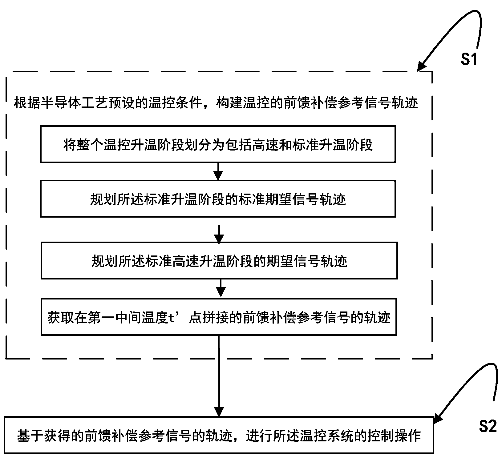
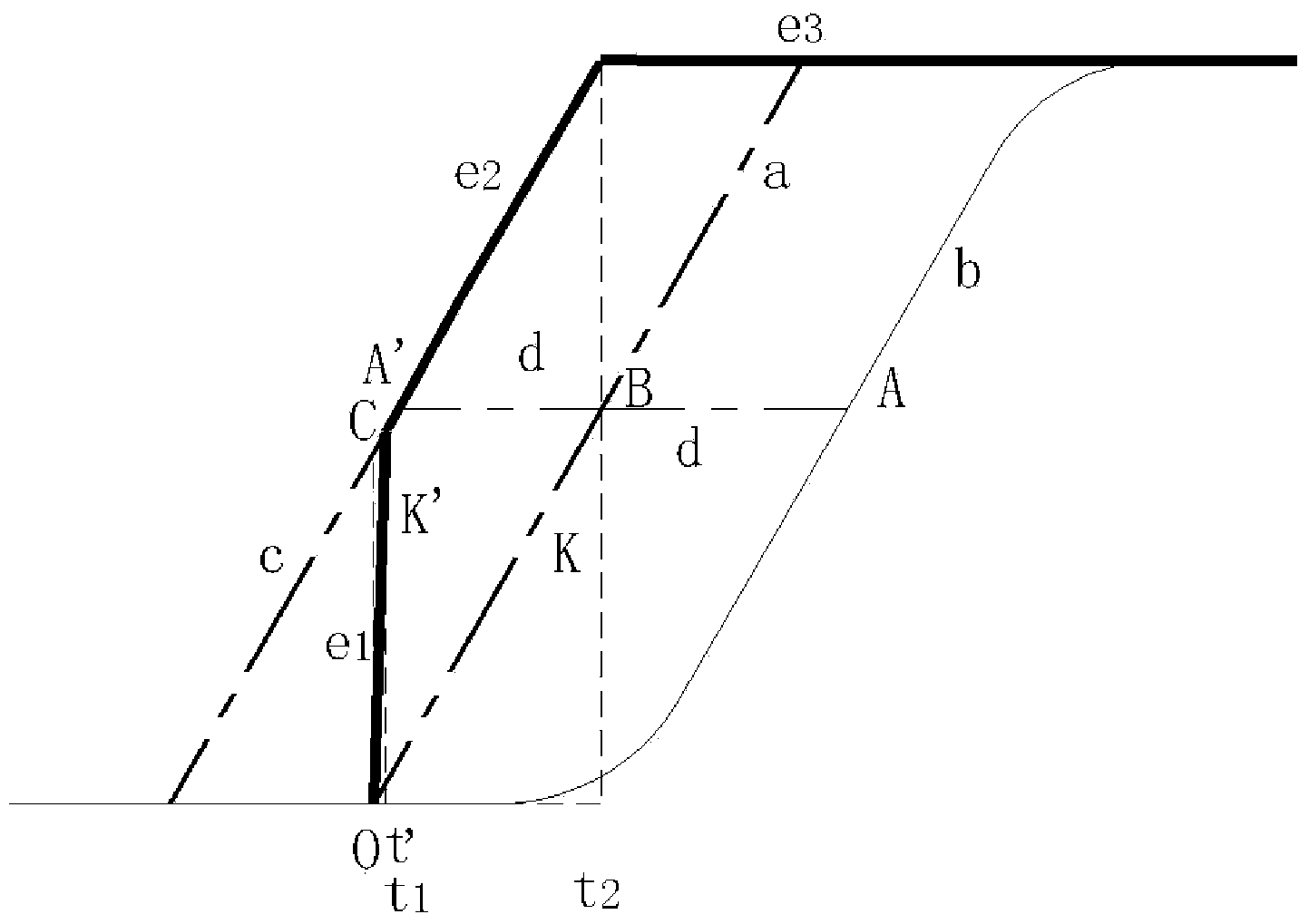
[0038] see image 3 , image 3 This is a schematic diagram of a preferred embodiment of the process of setting a feedforward reference signal trajectory in which the temperature rising control process is divided into a high-speed heating stage and a standard heating stage according to the present invention. like figure 2 and 3 As shown, step S1 can be specifically divided into the following steps:

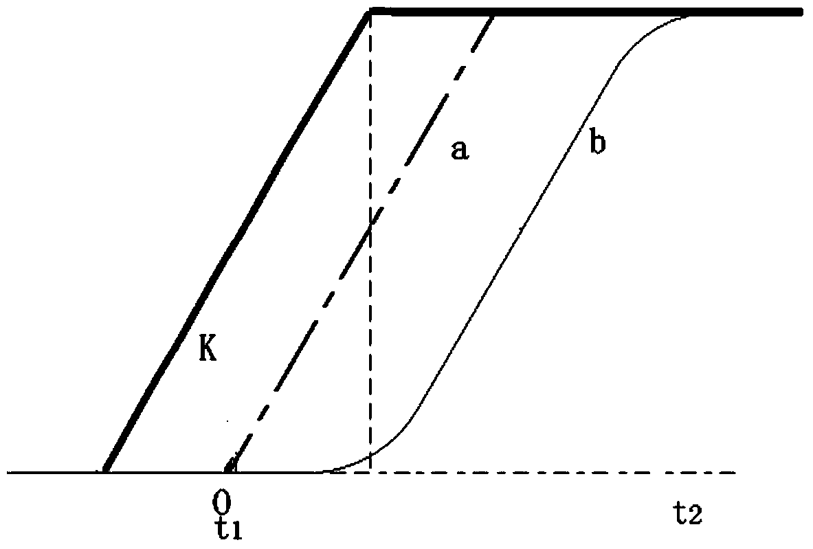
[0039] Step S11: Divide the whole temperature-controlled heating stage into a high-speed heating stage T' and a standard heating stage T, and the high-speed heating stage T' completes the heating process from the initial temperature t to the first intermediate temperature t' (i.e., as shown in Fig. image 3 The heating process in the time period from 0 to t1 shown), the standard heating stage T completes the heating process from the first intermediate temperature t' to the target temperature T (that is, as image 3 the heating process in the time period t1 to t2 shown).

[0040...

Embodiment 2

[0049] In order to prevent the temperature control system from generating a large overshoot during the temperature stabilization stage, in this embodiment, the method of the embodiment can also be improved. please combine figure 2 see Figure 4 , Figure 4 For the present invention, the standard temperature rise stage of the temperature control process (that is, as image 3 The shown heating process in the time period from t1 to t2) is further divided into a first heating stage and a second heating stage, a schematic diagram of a preferred embodiment of the process of setting the feedforward reference signal trajectory. like Figure 4 As shown, the standard heating stage T includes the first heating stage (ie, as Figure 4 The heating process in the time period from t1 to t2 shown) and the second heating stage (that is, as Figure 4 The heating process in the time period from t2 to t3 shown), the first heating stage completes the heating process from the first intermedia...


PUM


Abstract

Disclosed is a temperature control method of semiconductor technology equipment with feedforward compensation. The semiconductor technology equipment comprises temperature control devices in one or more temperature control areas. The method comprises the steps that according to the preset temperature control condition of a semiconductor technology, feedforward compensation reference signal tracks of the temperature control devices are constructed, the whole temperature control temperature rise period is divided into a high-speed temperature rise period and a standard temperature rise period, the temperature rise process from initial temperature t to first intermediate temperature t' is completed in the high-speed temperature rise period, and the temperature rise process from the first intermediate temperature t' to target temperature T is completed in the standard temperature rise period; reference signal tracks in the standard temperature rise period meet the preset temperature control condition, and the temperature rise speed of the high-speed temperature rise period is higher than that of the standard temperature rise period; control operation of the temperature control system is carried out based on the obtained feedforward compensation reference signal tracks. The influence of the time lag of the temperature control system can be weakened, the temperature rise effect of a furnace can be improved, and the productivity of the semiconductor technology equipment can be improved.

Description

technical field [0001] The invention belongs to the technical field of integrated circuit manufacturing, and relates to a temperature control method of semiconductor process equipment with feedforward compensation, and more particularly, to a reference signal trajectory planning method applied to temperature control of semiconductor process equipment. Background technique [0002] At present, the design of semiconductor devices is developing rapidly in the direction of high density and high integration, which puts forward higher and higher requirements for new processes, new technologies and new equipment of semiconductor integrated circuits. As one of the process equipment in the pre-process of the integrated circuit production line, the semiconductor process equipment plays an important role in the silicon wafer production and manufacturing processes such as diffusion, annealing, alloying, oxidation, and thin film growth. The temperature required to be precisely controlled ...

Claims


Application Information

Patent Timeline
IPC IPC(8): G05D23/00
Inventor 王峰付运涛刘晨曦
Owner BEIJING NAURA MICROELECTRONICS EQUIP CO LTD
Features
  • R&D
  • Intellectual Property
  • Life Sciences
  • Materials
  • Tech Scout
  • Unparalleled Data Quality
  • Higher Quality Content
  • 60% Fewer Hallucinations
Learn More