
Centrifugal pump flow prediction method based on power and differential pressure

A flow prediction, centrifugal pump technology, applied in pump control, non-variable-capacity pumps, special data processing applications, etc., can solve problems such as high cost, poor integration, and inability to effectively predict flow

Active Publication Date: 2015-01-21
ZHEJIANG COLLEGE OF ZHEJIANG UNIV OF TECHOLOGY
View PDF6 Cites 19 Cited by
  • Summary
  • Abstract
  • Description
  • Claims
  • Application Information

AI Technical Summary

Problems solved by technology

[0005] The technical problem to be solved by the present invention is that the existing centrifugal pump flow measurement or prediction method has the following disadvantages: 1) high cost and poor integration; A certain blind area; 3) There are specific requirements for the distribution of the axial force and radial force on the impeller of the centrifugal pump

Method used


Image

  • Centrifugal pump flow prediction method based on power and differential pressure
  • Centrifugal pump flow prediction method based on power and differential pressure
  • Centrifugal pump flow prediction method based on power and differential pressure

Examples


Embodiment Construction

[0093] The present invention will be further described in detail with reference to the accompanying drawings and embodiments.

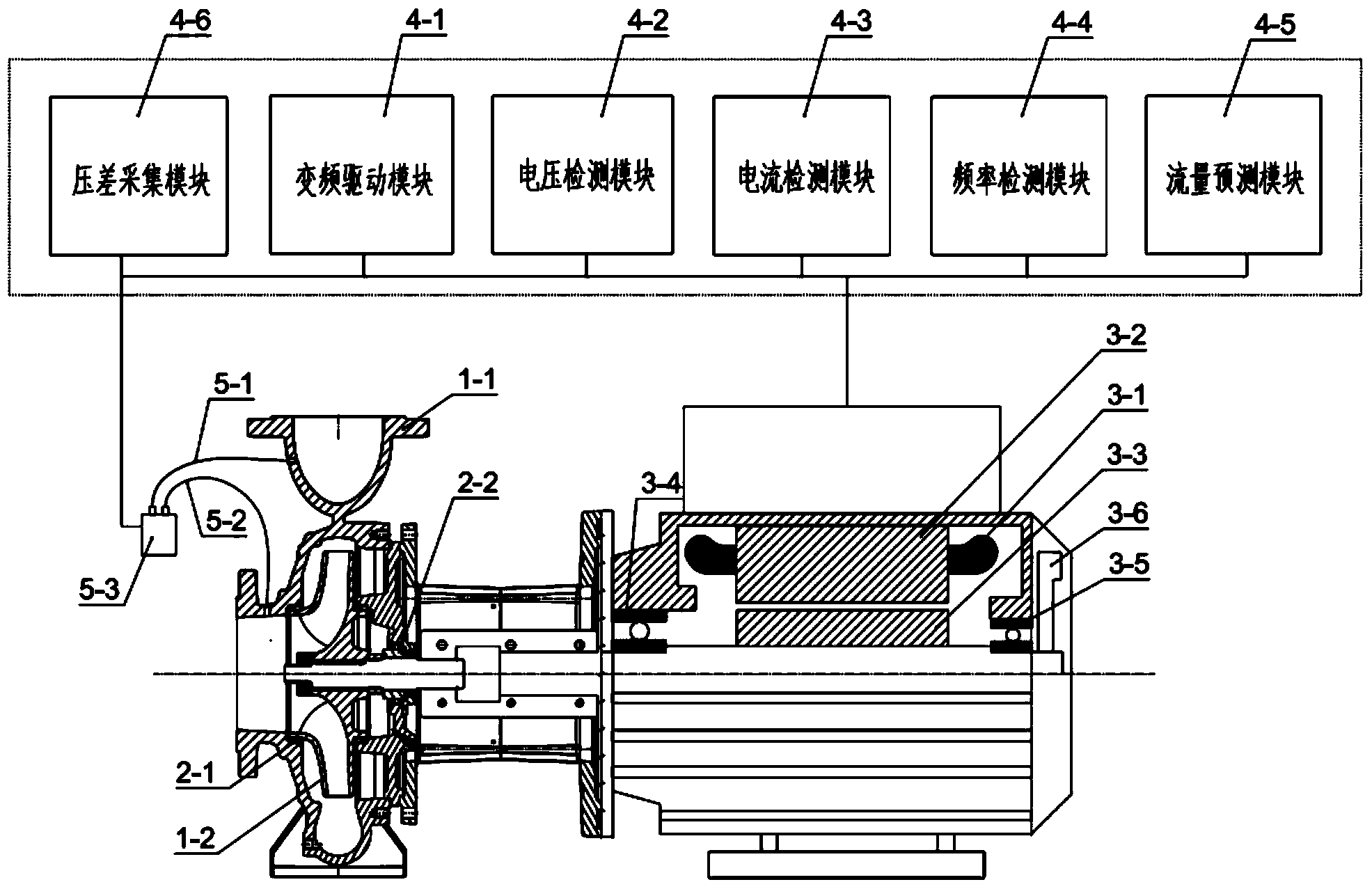
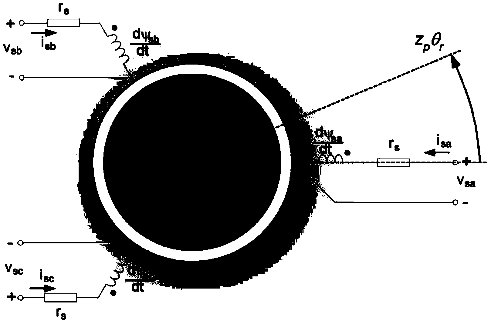
[0094] combine figure 1 , figure 2 , image 3 , Figure 4 , Figure 5 and Figure 6 , a specific implementation of a centrifugal pump flow prediction method based on power and pressure difference is shown below:

[0095] Step 1. Construct a centrifugal pump flow prediction model based on the 'Gray-box modeling' theory;

[0096] According to the principle of energy conservation, the centrifugal pump is divided into three modules as a whole, namely, the motor module (6-1), the mechanical module (6-2) and the hydraulic module (6-3), and each module has corresponding input parameters And the output parameters and the internal energy transfer model, here it is defined as a 'gray box' module, where the motor module is the first 'gray box'; the mechanical module is the second 'gray box'; the hydraulic module is the third 'gray box' '. For the motor ...


PUM


Abstract

Disclosed is a centrifugal pump flow prediction method based on measurement of power and differential pressure. The centrifugal pump flow prediction method is characterized by including steps that 1, a whole centrifugal pump is respectively divided into a motor module, a mechanical model and a hydraulic power module on the basis of a 'gray box' construction theory; 2, a whole flow prediction mathematical model of the centrifugal pump is built on the basis of system analysis; 3, local establishment of a motor output power prediction mathematical model is performed on the basis of a motor inner loss model; 4, local establishment of a mechanical transmission part output power (or centrifugal pump input power) prediction mathematical model is performed on the basis of a mechanical loss model; 5, local establishment of a model among centrifugal pump input power, flow and rotating speed and a model among centrifugal pump differential pressure, flow and rotating speed is performed on the basis of a fluid flow loss model; 6, a centrifugal pump flow prediction model based on power (rotating speed and torque) and differential pressure is established by combination with a motor mathematical model, a mechanical mathematical model and a hydraulic power mathematical model; 7, the centrifugal pump flow prediction model is corrected by means of a compensation algorithm, and the flow prediction accuracy is improved.

Description

technical field [0001] The invention belongs to the field of measurement and control of centrifugal pumps, in particular to a method for predicting the flow rate of centrifugal pumps based on power and differential pressure, which is mainly used to quickly and accurately predict the flow rate of centrifugal pumps, so as to monitor the operating status of centrifugal pumps in real time, and at the same time Combining the flow value and the temperature difference value can be used to evaluate the heat or cold consumed by the overall thermal system or air conditioning system equipped with the centrifugal pump within a unit time. The centrifugal pump integrated with the flow prediction algorithm effectively replaces the function of the flow meter in the system, greatly reducing the operating cost of the system. Background technique [0002] Centrifugal pumps are widely used in HVAC, municipal water supply, petrochemical and many other fields. As users pay more and more attentio...

Claims


Application Information

Patent Timeline
Patent Type & Authority Applications(China)
IPC IPC(8): G06F19/00
CPCF04D15/0088
Inventor 吴登昊任芸杨友东蒋兰芳牟介刚刘健
Owner ZHEJIANG COLLEGE OF ZHEJIANG UNIV OF TECHOLOGY
Learn More