Projector calibration method based on lens distortion rule

A lens distortion and calibration method technology, applied in the field of computer vision, can solve the problems such as being unsuitable for a large field of view optical measurement system, low accuracy requirements, ignoring lens distortion, etc., to achieve flexible operation, improve calibration accuracy, and avoid errors.

Inactive Publication Date: 2015-01-21
NANJING UNIV OF POSTS & TELECOMM
View PDF6 Cites 32 Cited by
  • Summary
  • Abstract
  • Description
  • Claims
  • Application Information

AI Technical Summary

Problems solved by technology

[0006] 1) The direct linear transformation calibration method, using the ideal pinhole model, ignores the lens distortion, and is only suitable for the case of a small field of view;
[0007] 2) The two-step calibration method with radial arrangement constraints only considers the first-order radial distortion, whil

Method used


Image

  • Projector calibration method based on lens distortion rule
  • Projector calibration method based on lens distortion rule
  • Projector calibration method based on lens distortion rule

Examples


Embodiment Construction

[0043] The invention will be described in further detail below in conjunction with the accompanying drawings.

[0044]In order to better understand the present invention, the specific implementation manners of the present invention will be further described below in conjunction with the accompanying drawings and examples. This embodiment is only used to describe the present invention and is not intended to limit the scope of the present invention. In addition, it should be understood that, based on the embodiments of the present invention, all other embodiments obtained by persons of ordinary skill in the art without creative efforts shall fall within the protection scope of the present invention.

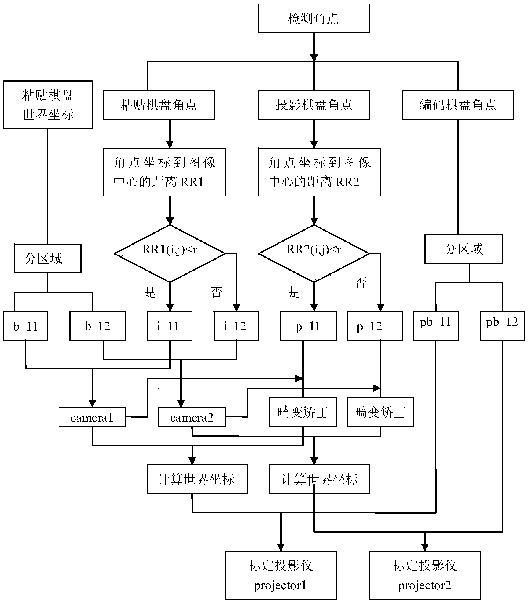
[0045] The flow chart of concrete steps of the present invention is as figure 1 As shown, the specific steps of applying the present invention for projector calibration are as follows:

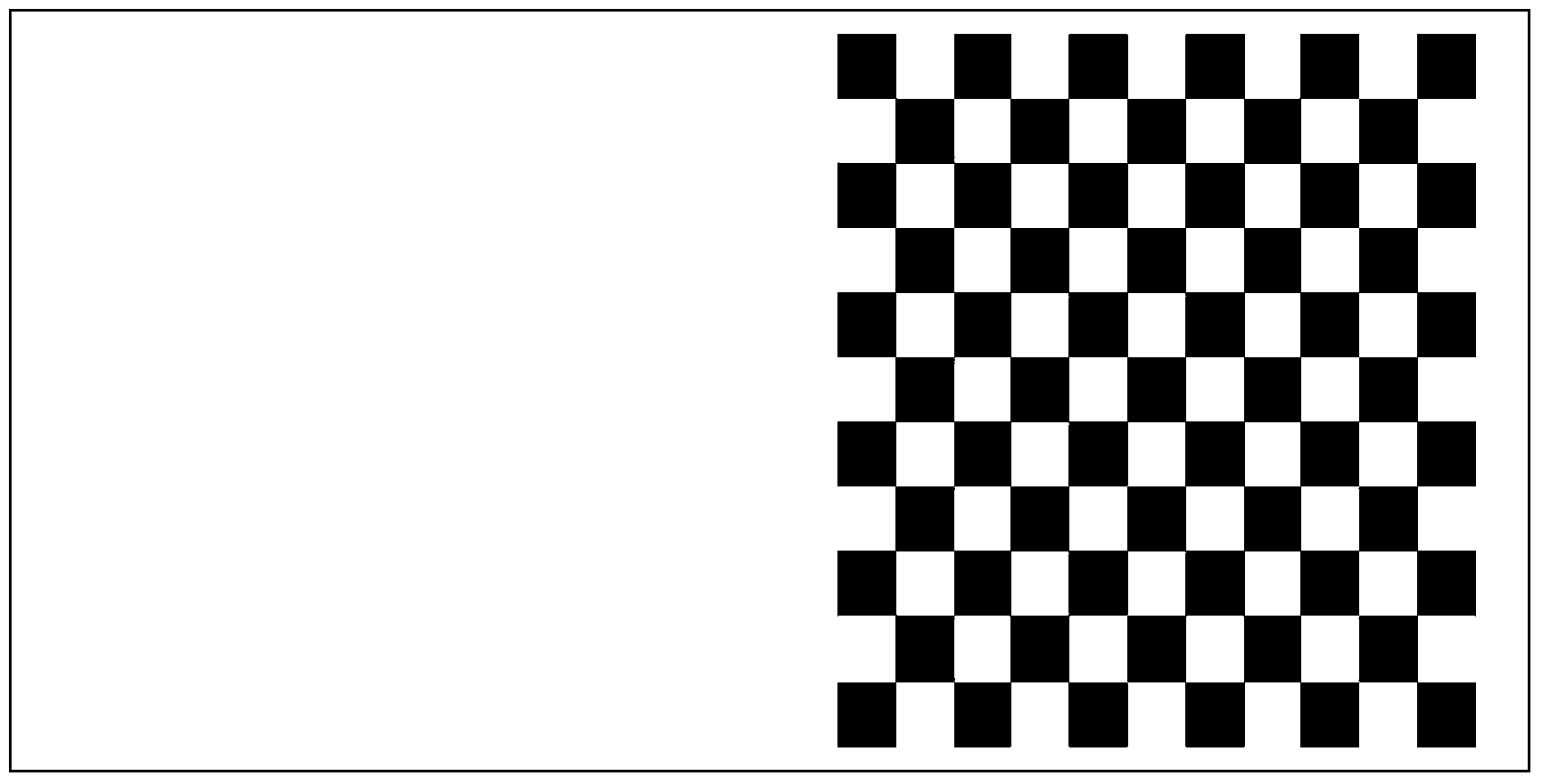
[0046] Step 1: First, use the checkerboard as the feature points to make a plane calibration ...


PUM


Abstract

The invention discloses a projector area calibration method by utilizing concentric circular rings on the basis of a lens distortion rule, and solves a problem of low calibration precision when a field of view is enlarged at present while a problem of insufficient optical lens distortion processing is solved. The method comprises the following steps: firstly, projecting a specially-designed checkerboard image onto a plane calibration board by utilizing a DLP (Digital Light Processing) projector, and capturing a calibration object image which contains a pasting checkerboard and a projection checkerboard by a CCD (Charge Coupled Device) camera; changing the position of the plane calibration board for multiple times to obtain multiple pairs of calibration object images; according to the lens distortion rule, taking the center of each calibration image as a center of a circle, calculating distance between each angle point to the center of a circle, and comparing the distance with a given radius value to divide the concentric circular ring areas; on the basis of each concentric circular ring, calibrating a camera, carrying out distortion correction to the data of the projection checkerboard by utilizing calibration parameters so as to calibrate the projector to obtain the internal and external parameters of the projector of a corresponding area; and repeating the above operations to the circular ring areas to finish the calibration of the projector.

Description

technical field [0001] The invention relates to the technical field of computer vision, in particular to a projector calibration method based on the law of lens distortion. Background technique [0002] In order to obtain the corresponding relationship between the two-dimensional points on the object plane of the projector (the plane of the spatial light modulator in the projector, hereinafter referred to as the object plane) and the three-dimensional points in the actual physical space, the projector needs to be calibrated. The main purpose of the so-called calibration is to obtain the internal geometric and optical characteristics of the projector (that is, internal parameters), and its positional relationship with respect to the spatial coordinate system (that is, external parameters). [0003] The optical structure of the projector is the same as that of the camera with telecentric optical structure, but the optical path is opposite, so the optical model of the projector...

Claims


Application Information

Patent Timeline
IPC IPC(8): G06T7/00
CPCG06T7/80
Inventor 高志强陈会密保秀
Owner NANJING UNIV OF POSTS & TELECOMM
Why Eureka
Try Eureka