
Inverter synchronous grid connection method

A technology of inverters and contactors, which is applied to inverters with AC side soft start function and their grid-connected fields, which can solve the problems of high system construction cost, AC voltage phase amplitude error, etc., and prolong the service life , The effect of overcoming the problem of high current impact on the internal devices of the inverter and the grid-connected switch

Active Publication Date: 2015-01-21
SHENZHEN WINLINE TECH
View PDF7 Cites 24 Cited by
  • Summary
  • Abstract
  • Description
  • Claims
  • Application Information

AI Technical Summary

Problems solved by technology

[0003] At present, there are two methods of soft start: DC side soft start and AC side soft start. Chinese patent CN102545678A discloses an inverter and its start-up method, which uses a DC side soft start, including sequentially cascaded DC side switches. , bus capacitor component, power module, output filter component, grid-connected contactor, and AC circuit breaker, the DC side switch is connected to the DC side input, the AC circuit breaker is connected to the grid, and the input and output sides of the soft start device are respectively It is connected with the DC side input and the power module. This method needs to establish a special booster device on the DC side, and the system construction cost is relatively high.
[0004] Chinese patent CN103887824A discloses a control system and control method for voltage loop ripple compensation of photovoltaic grid-connected inverters. It adopts soft start on the AC side, but because it simply establishes a certain voltage on the bus capacitor, it is connected to the power grid. The AC voltage on the side of the grid has a large error in the voltage phase amplitude, so the grid connection process will still cause a large grid connection impact

Method used


Image

  • Inverter synchronous grid connection method
  • Inverter synchronous grid connection method

Examples


Embodiment Construction

[0023] The principles and features of the present invention will be clearly and completely described below in conjunction with the accompanying drawings in the embodiments of the present invention. Apparently, the described embodiments are only used to explain the present invention, not to limit the scope of the present invention.

[0024] Embodiments of the present invention will be described in detail below in conjunction with the accompanying drawings.

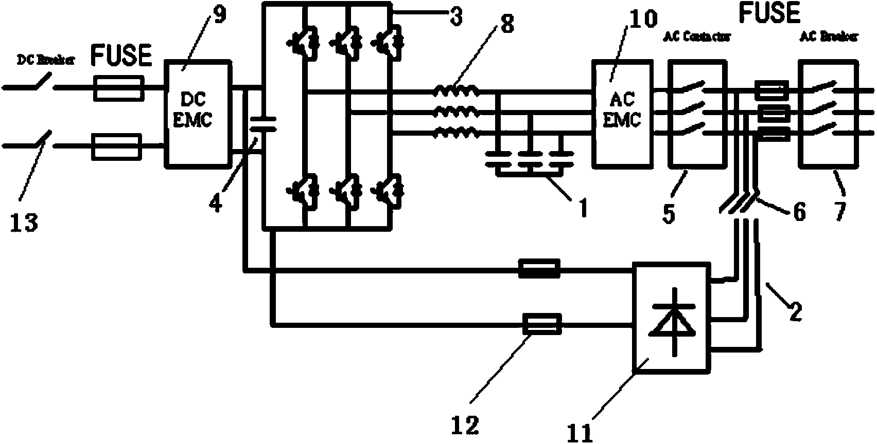
[0025] figure 1 It is a schematic diagram showing an inverter adopting an inverter AC side soft start device according to an embodiment of the present invention. Such as figure 1 As shown, the inverter of the present invention is, for example, a photovoltaic grid-connected inverter, which mainly includes a DC side switch 13, a DC EMC filter 9, a bus capacitor component 4, a power module 3, an inductor 8, and an output filter component connected in sequence 1. AC EMC filter 10, grid contactor 5, soft start circuit 2 and AC...


PUM


Abstract

The invention relates to an inverter synchronous grid connection system and an inverter synchronous grid connection method. The inverter synchronous grid connection system comprises a DC (Direct Current) side switch, a DC EMC (Electro Magnetic Compatibility) filter, a bus capacitor assembly, a power module, an inductor, an output filter assembly, an AC (Alternating Current) EMC filter, a grid connection contactor, a soft start circuit and an AC side circuit breaker which are sequentially connected; the soft start circuit is formed by a prechargd contactor, a rectification bridge and a series resistor; one end of the soft start circuit is connected to the bus capacitor assembly at the DC side and the other end of the soft start circuit is connected with the AC side circuit breaker. Voltage and phase values of the bus capacitor assembly are continuously detected and when the voltage and phase values are the same with those of a power grid, grid connected power generation is carried out, and thus, current impact in the grid connection process is reduced and the service lives of devices, particularly an expensive large-current grid connection switch, inside an inverter are obviously prolonged.

Description

technical field [0001] The invention relates to the technical field of inverters, in particular to an inverter with an AC side soft start function and a grid connection method thereof. Background technique [0002] The DC power generated by photovoltaic modules is usually transformed into AC power that matches the grid through a grid-connected photovoltaic inverter, and then delivered to the grid. The inverter is generally composed of a DC boost circuit and an inverter circuit. It is a power adjustment device composed of semiconductor devices and is mainly used for DC conversion to AC. In the application of high-power UPS, wind power, photovoltaic inverter and energy storage inverter, a large number of DC bus capacitors and AC output filter capacitors are used, in order to reduce the current impact on the grid-connected switch, grid and capacitor at the moment of grid-connection , Generally, the method of series resistor current limiting soft start is adopted. [0003] At ...

Claims


Application Information

Patent Timeline
IPC IPC(8): H02M1/36H02J3/38
CPCH02J3/38H02M1/36
Inventor 吴建华朱建国
Owner SHENZHEN WINLINE TECH
Learn More