Novel magnetic energy electric generator

A generator and magnetic energy technology, applied in the direction of generators/motors, electrical components, electromechanical devices, etc., can solve the problems of generators being difficult, unable to be formally put into use, hindering rotor rotation, etc., and achieve economical operating costs, simple structure, and low cost. low effect

Pending Publication Date: 2015-01-21
陈新培
View PDF11 Cites 4 Cited by
  • Summary
  • Abstract
  • Description
  • Claims
  • Application Information

AI Technical Summary

Problems solved by technology

However, there are always various problems in this kind of products, one of which is that the technical problem of mutual interference between the magnetic field generated by the induced current and the magnetic field of the permanent magnet cannot be solved. During the operation of the generator, the coil induced current The generated magnetic field always hinders the rotation of the rotor as a permanent magnet. Most of the results are: the mechanical energy provided to the generator is always greater than the electrical energy generated by the generator, even if the electrical energy generated by some generators is greater than the mechanical energy supplied to it , and because the input-to-output ratio of the generator is unacceptable, it cannot be formally put into use

Method used


Image

  • Novel magnetic energy electric generator
  • Novel magnetic energy electric generator
  • Novel magnetic energy electric generator

Examples


Embodiment 1

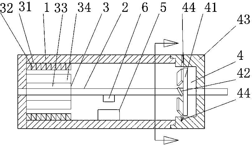
[0014] Such as figure 1 , figure 2 , image 3 , Figure 4 As shown, a new type of magnetic energy generator includes a mechanical part and an electronic control part. The mechanical part includes a housing 1, a rotating shaft 2 installed in the housing 1, a generator device 3 arranged at one end of the rotating shaft 2 and a generator device located at one end of the rotating shaft 2. The magnetic energy driving device 4 at the other end of the rotating shaft 2, the inner side of the housing 1 is provided with an electromagnetic induction switch 5, and the rotating shaft 2 is provided with an induction magnetic block 6 corresponding to the electromagnetic induction switch 5.

Embodiment 2

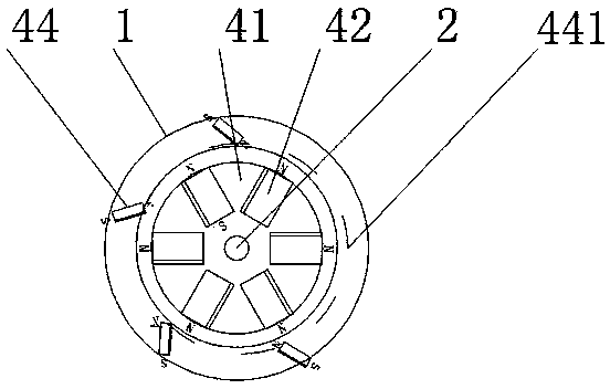
[0016] Such as figure 1 , figure 2 As shown, the generator device 3 includes a stator core 31 disposed inside the casing 1, a stator winding 32 wound on the stator core 31, an induction rotor 33 disposed inside the stator winding 32, and an induction rotor wound The excitation winding 34 on the 33, the induction rotor 33 is installed on the rotating shaft 2, and the magnetic energy driving device 4 includes a rotating disk 41 arranged on the rotating shaft 2, an internal permanent magnet 42 radially fixed on the end surface of the rotating disk 41, a sleeve The end cover collar 43 located on the outside of the turntable 41, the outer permanent magnet 44 installed in the end cover collar 43, the N pole of the inner permanent magnet 42 faces outward in the radial direction, and the inner permanent magnet 42 is arranged along the turntable 41. The end face is obliquely installed, the side of the inner permanent magnet 42 forms an acute angle of 0 to 90 degrees with the end face...

Embodiment 3

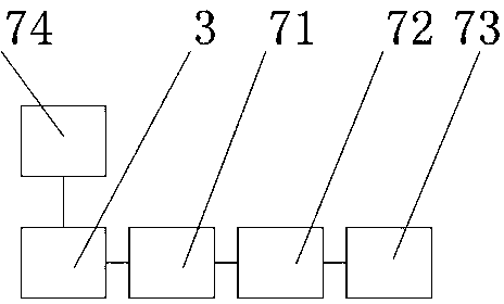
[0018] Such as image 3 , Figure 4 As shown, the electronic control part is formed by electrically connecting the stator winding 32 of the generator device 3, the electromagnetic induction switch 5, the bridge rectifier circuit 71, the voltage stabilizing circuit 72, and the constant current circuit 73. The bridge rectifier Circuit 71, voltage stabilizing circuit 72, constant current circuit 72 are connected in series, the stator winding 32 of generator device 3 is connected in series with electromagnetic induction switch 5, and described electromagnetic induction switch 5 is reed switch, and the stator winding 32 of generator device 3 The winding 32 is connected in series, and the reed switch is a normally open switch. When the induction magnetic block 6 on the rotating shaft 2 is close to the reed switch, the reed switch is closed and charged externally. When the induction magnetic block 6 on the rotating shaft 2 is far away from the reed switch, Reed switch disconnection ...


PUM


Abstract

The invention relates to the field of electric generators, in particular to a novel magnetic energy electric generator. The novel magnetic energy electric generator comprises a mechanical part and an electronic control part. The mechanical part comprises a shell, a rotating shaft arranged in the shell, an electric generator device arranged at one end of the rotating shaft, and a magnetic energy driving device arranged at the other end of the rotating shaft. An electromagnetic induction switch is arranged inside the shell. An induction magnetic block is arranged on the rotating shaft and is matched with and corresponds to the electromagnetic induction switch. Due to the structure, magnetic energy can be converted into kinetic energy to be output, the conversion from magnetic energy to electric energy is achieved, the whole running process is free of pollution and environmentally friendly, almost no extra original power needs to be provided by the outside world after the novel magnetic energy electric generator runs, and the novel magnetic energy electric generator is simple in structure, low in manufacturing cost and economical in running cost.

Description

technical field [0001] The invention relates to the field of generators, in particular to a novel magnetic energy generator. Background technique [0002] The magnetic field is actually a kind of energy, but it is the same as the gravitational field, it is a kind of energy generated because of the relative position. There are many examples of kinetic energy generated by two objects in the system without external force. For example, two planets are approaching each other under the action of universal gravitation, and the speed is getting faster and faster. This is the result of the release of gravitational potential energy between them. Only a changing magnetic field can transfer energy, and the magnetic field of a permanent magnet is constant. , with the rapid development of social production, people need a lot of energy. Over the years, people have designed many magnetic energy generators, including the magnetic part and the power generation part. The magnetic part is comp...

Claims


Application Information

Patent Timeline
Patent Type & Authority Applications(China)
IPC IPC(8): H02N11/00H02K53/00
CPCH02N11/002
Inventor 陈新培郭献培
Owner 陈新培
Why Eureka
Try Eureka