
Hydraulic clamp of numerical control lathe

A technology of hydraulic fixtures and CNC lathes, applied in clamping, manufacturing tools, supports, etc., can solve the problems of poor size consistency of parts, high labor intensity of loading and unloading, and large fluctuation range of precision, and achieve low manufacturing ease and uniform pressing force Good performance and reliability, and the effect of improving processing efficiency

Inactive Publication Date: 2015-01-28
中国航发湖南南方宇航工业有限公司
View PDF6 Cites 6 Cited by
  • Summary
  • Abstract
  • Description
  • Claims
  • Application Information

AI Technical Summary

Problems solved by technology

The traditional car counting fixture adopts manual mechanical fixture, which is inconvenient for clamping. Due to the inconsistency of the operator's pressing force during each processing, the dimensional accuracy of the parts fluctuates widely, resulting in poor consistency in the size of the parts, and the labor intensity of loading and unloading is high. Long time and low processing efficiency

Method used


Image

  • Hydraulic clamp of numerical control lathe
  • Hydraulic clamp of numerical control lathe

Examples


Embodiment Construction

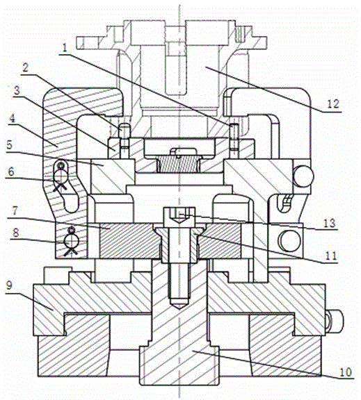
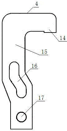
[0012] The numerical control lathe hydraulic clamp of the present invention comprises a body 5 , a positioning block 3 , a lever 7 , a connection plate 9 and a tie rod 10 . The body 5 is composed of a positioning platform and a supporting cylinder. There are three sliding bearings evenly distributed on the positioning platform. The sliding bearings are provided with sliding pins 6, and three through grooves are evenly distributed on the supporting cylinder. The positioning block 3 placed on the body 5 is provided with a diamond-shaped positioning pin 1 and a circular positioning pin 2 . The lever 7 is made of three connecting rods uniformly distributed on the disc and the circumference, the center of the disc is provided with a connecting hole, and a spherical bushing 11 is built in the connecting hole. The connecting rod is connected with a hook-shaped pressing plate 4, and the connecting rod and the hook-shaped pressing plate 4 are rotatably connected by a rotating pin 8. T...


PUM


Abstract

The invention relates to a hydraulic clamp of a numerical control lathe. The hydraulic clamp comprises a body, a positioning lock, a lever, a connecting disc and a pull rod. The hydraulic clamp is characterized in that the body consists of a positioning platform and a support cylinder, wherein three slide support seats are uniformly distributed on the positioning platform, and are respectively provided with a slide pin, three through grooves are uniformly distributed in the support cylinder, the lever consists of a circular disc and three connecting rods, the three connecting rods are uniformly distributed on the circumference and are connected with hook-shaped press plates, the lever is connected with the pull rod by a connecting bolt, the circular disc and the connecting rods of the lever are respectively and glidingly connected with the support cylinder and the through grooves, and the body is tightened on the connecting disc by screws. The hydraulic clamp has the advantages that the structure is simple, the manufacturing is easy, and the cost is low; a spherical bushing is arranged in a connecting hole of the lever, and the lever can rotate around the spherical bushing in the vertical and circumferential directions; when the clamp is used for parts of shaped casings, the uniformity and reliability of the pressing force for pressing the parts are good, the installation and detachment of the parts are convenient, the installation and detachment time of the parts is shortened, the processing efficiency and processing quality of the parts are improved, and the economy is good.

Description

technical field [0001] The invention relates to a fixture, in particular to a numerical control lathe hydraulic fixture used for special-shaped shell parts. Background technique [0002] In the machining industry, it is common to see the need for several cars to process special-shaped shells. The irregular points are mainly (1) the pressing surface is a rough rough surface; (2) the three pressing points are not evenly distributed. The jig for the number of vehicles rotates at high speed, so the design requirements for the jig are high, such as the jig should be light and reliable, and the dynamic balance should be good. The traditional car counting fixture adopts manual mechanical fixture, which is inconvenient for clamping. Due to the inconsistency of the operator's pressing force during each processing, the dimensional accuracy of the parts fluctuates widely, resulting in poor consistency in the size of the parts, and the labor intensity of loading and unloading is high. ...

Claims


Application Information

Patent Timeline
Patent Type & Authority Applications(China)
IPC IPC(8): B23Q3/00
CPCB23B31/302
Inventor 刘春花李义斌李峥安王艳
Owner 中国航发湖南南方宇航工业有限公司
Learn More