Gear grinding machine

A gear grinding machine and grinding head technology, applied in the direction of gear cutting machine, grinding machine parts, gear teeth, etc., can solve the problems of low efficiency, high cost, difficult maintenance, etc., to improve processing efficiency, low cost, easy to use maintenance effect

Active Publication Date: 2015-01-28
陈明友
View PDF10 Cites 2 Cited by
  • Summary
  • Abstract
  • Description
  • Claims
  • Application Information

AI Technical Summary

Problems solved by technology

[0002] The existing gear grinding machines are mainly CNC models, which mainly have the following disadvantages: 1. The gear grinding machine has...

Method used


Image

  • Gear grinding machine
  • Gear grinding machine
  • Gear grinding machine

Examples


Embodiment Construction

[0030] The principles and features of the present invention are described below in conjunction with the accompanying drawings, and the examples given are only used to explain the present invention, and are not intended to limit the scope of the present invention.

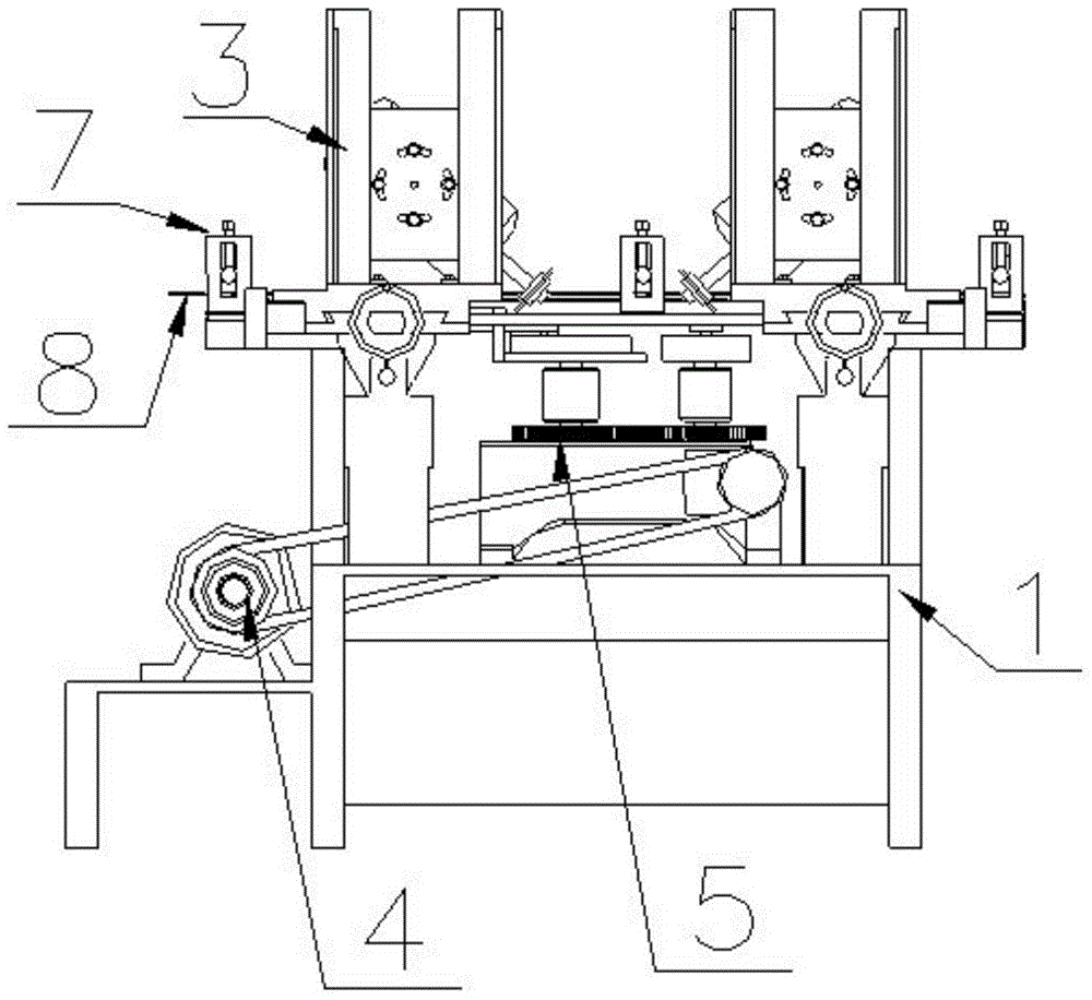
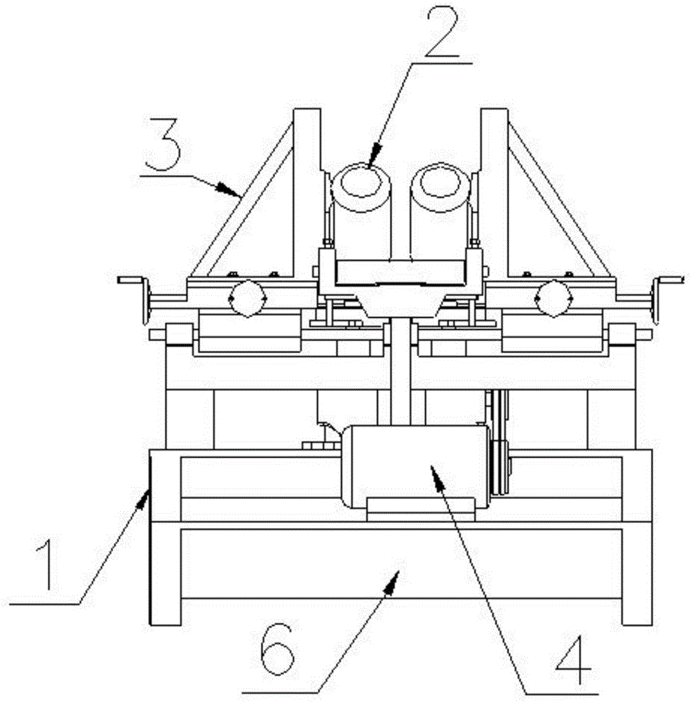
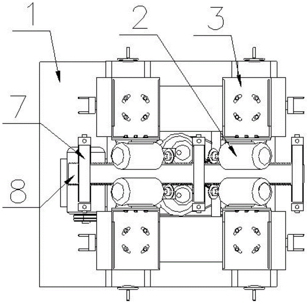
[0031] Such as Figure 1 to Figure 4 As shown, a gear grinding machine includes a frame 1, a grinding head device 2, a grinding head adjustment pallet 3, a motor 4, a workpiece positioning clamping drag mechanism 5 and a cooling device 6, and the grinding head adjustment pallet 3 Placed on the upper end surface of the frame 1, the grinding head device 2 is fixed on one side of the grinding head adjusting pallet 3, and the grinding head adjusting pallet 3 drives the grinding head device 2 to move, The motor 4 is placed on one side of the frame 1, the workpiece positioning clamping drag mechanism 5 is placed in the frame 1 at the lower end of the grinding head device 2, and the motor 4 is connected to the workpiece po...


PUM


Abstract

The invention relates to a gear grinding machine which comprises a machine frame, grinding head devices, grinding head adjusting plates, a motor, a workpiece positioning, clamping and dragging mechanism and a cooling device, wherein the grinding head adjusting plates are arranged on the upper end surface of the machine frame; the grinding head devices are fixedly arranged on one sides of the grinding head adjusting plates; the grinding head adjusting plates drive the grinding head devices to move; the motor is arranged on one side of the machine frame; the workpiece positioning, clamping and dragging mechanism is arranged in the machine frame at the lower end of the grinding head device; the motor is connected with the workpiece positioning, clamping and dragging mechanism through a belt; the workpiece positioning, clamping and dragging mechanism drives the grinding head adjusting plates to move; the cooling device is arranged at the lower end of the workpiece positioning, clamping and dragging mechanism. Compared with the prior art, the gear grinding machine has the benefits that the structure is simple, the cost is low, the maintenance is convenient, bilateral gear grinding can be simultaneously performed, and the gear grinding precision is high.

Description

technical field [0001] The invention relates to the technical field of mechanical processing devices, in particular to a gear grinding machine. Background technique [0002] The existing gear grinding machines are mainly numerically controlled models, which mainly have the following disadvantages: 1. The gear grinding machine is complex in structure, high in cost, and difficult to maintain; 2. The gear grinding is only a unilateral operation, with low efficiency and low precision. Contents of the invention [0003] The technical problem to be solved by the present invention is to provide a gear grinding machine with simple structure, low cost, convenient maintenance, capable of simultaneously grinding both sides, and high grinding precision. [0004] The technical solution of the present invention to solve the above-mentioned technical problems is as follows: a gear grinding machine, including a frame, a grinding head device, a grinding head adjustment support plate, a mot...

Claims


Application Information

Patent Timeline
IPC IPC(8): B24B19/00B24B41/00B23F5/02B23F9/02B23F23/06B23F23/00
CPCB23F5/02B23F9/02B23F23/06Y02P70/10
Inventor 陈明友
Owner 陈明友
Why Eureka
Try Eureka