

Variable valve driving mechanism of engine
A driving mechanism and engine technology, applied in the direction of engine components, machines/engines, mechanical equipment, etc., can solve the problems of poor reliability and durability, increased cost, limited application, etc., to achieve simple and compact structure, easy manufacturing and assembly, and wide application. Effect
- Summary
- Abstract
- Description
- Claims
- Application Information
AI Technical Summary
Problems solved by technology
Method used
Image

Examples
Embodiment Construction
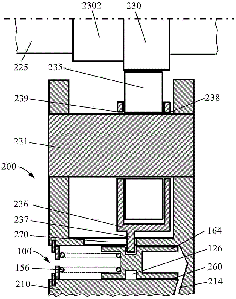
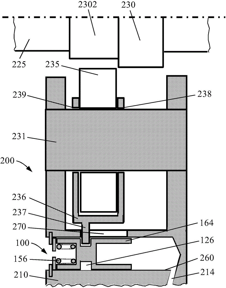
[0022] figure 1 and figure 2 Describes the positional relationship among relevant parts in the embodiment of the engine variable valve drive mechanism of the present invention. These components are an integral part of the valve train 200 of the engine. In this case, the cam roller 235 is rotatably mounted on a roller shaft 231 which is mounted on the component 210 . Component 210 can be a rocker arm of an overhead cam engine, or a cam follower of a pushrod engine (because people are familiar with engines, some engine parts, such as rocker arms, pushrods, and cam followers and valves, etc., not listed here). The roller driving mechanism 100 is arranged in the component 210 . The roller drive mechanism 100 here includes a spring 156 and a piston 164 . One side of the piston 164 (the left side in the figure) is subjected to the force of the spring 156, and the other side of the piston 164 (the right side in the figure) is subject to the force of the fluid (such as engine oi...
PUM
 Abstract
Description
Claims
Application Information