Plasma phase-changing control air inlet passage and control method

A technology of plasma and air inlet, which is applied in the field of air inlet, can solve the problems affecting engine performance, engine surge, parking, etc., and achieve the effects of reducing separation, increasing engine thrust, and sufficient fuel

Inactive Publication Date: 2015-01-28
NORTHWESTERN POLYTECHNICAL UNIV
View PDF3 Cites 3 Cited by
  • Summary
  • Abstract
  • Description
  • Claims
  • Application Information

AI Technical Summary

Problems solved by technology

[0003] However, in the actual flight process, the airflow will have flow separation at the inlet lip and S-shaped curve

Method used


Image

  • Plasma phase-changing control air inlet passage and control method
  • Plasma phase-changing control air inlet passage and control method
  • Plasma phase-changing control air inlet passage and control method

Examples


Embodiment Construction

[0017] Now in conjunction with embodiment, accompanying drawing, the present invention will be further described:

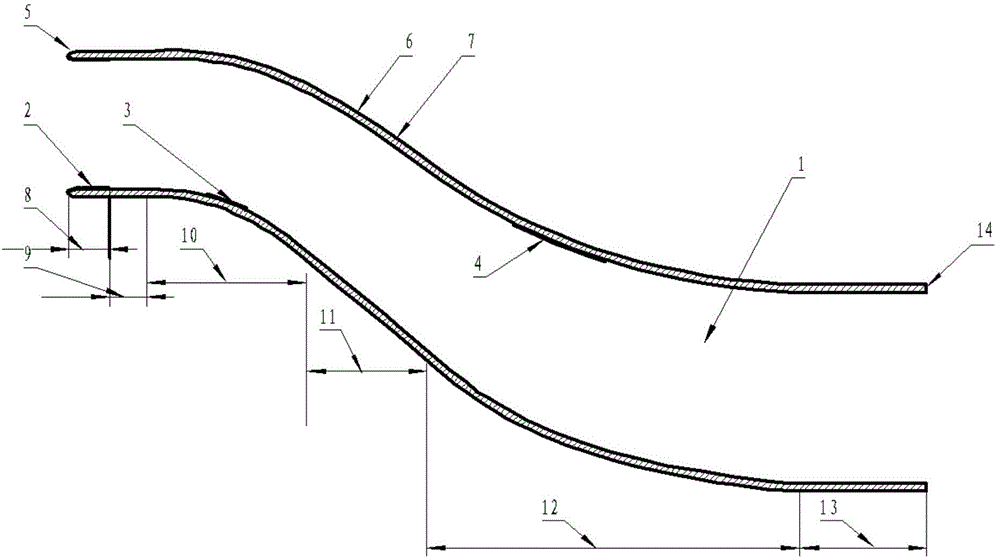
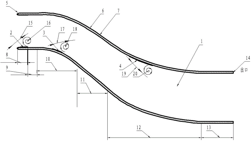
[0018] Phase-change flow control inlets based on bipolar plasma actuators, such as figure 2 As shown, the air intake form is: rectangular air inlet 100mm*84mm, circular outlet diameter 128mm, consisting of lip 8, throat 9, first bend 10, middle bend 11, second bend 12 and rear Straight segment 13 is composed. The first bipolar plasma actuator 2 is arranged at the lip 8, the second bipolar plasma actuator 3 is arranged in the airflow separation area of ​​the first bend, and the third bipolar plasma actuator 4 is arranged in the first bend 2 Bend airflow separation area.

[0019] When the airflow separates at the lip 8, the lip separation airflow 15 airflow moves away from the surface of the lip 8 and forms a lip vortex 16 in reverse motion, the same situation will occur at the first bend 10 and the second bend Road 12 appears, the 1st bend separation airflow 1...


PUM


Abstract

The invention relates to an air inlet passage capable of controlling the flow separation of airflow of the air inlet passage, bipolarity plasma exciters are respectively arranged on the lip position and the flowing separation corner position of the engine air inlet passage. When the airflow flows by the position to be subjected to flowing separation, the bipolarity plasma exciters are started, and air contacts the polarity plasma exciter on the position and is ionized to have phase change to form plasma state. The plasma is controlled by an electric field to be adsorbed to the surface of a lip to move backwards, air is continuously converted between plasma state and gaseous state in the movement process, the lip airflow is effectively controlled, and the flowing separation of the airflow is weakened and even eliminated. The air inlet passage has control capability on the airflow close to the wall surface, the separation situation of the airflow can be effectively alleviated, the working efficiency of the air inlet passage can be improved, the engine fuel is combusted adequately and rapidly under the combustion-supporting effect of the plasma, and the engine performance and the engine thrust force can be improved.

Description

technical field [0001] The invention belongs to an engine air intake device, in particular to an air intake channel capable of controlling air flow separation of the intake channel. Background technique [0002] The air intake duct of an aircraft is an important part of the aeropropulsion system, and it is a channel that provides air flow for the engine. A well-matched engine intake to the engine can improve aircraft tactical performance. On the other hand, aircraft stealth is also the goal pursued by various military powers. In response to the requirements of these two aspects, the S-shaped inlet is currently a choice that can take into account both. Its two-bend structure can make radar waves attenuate through multiple reflections in the air inlet, reducing the visible area of ​​the engine. [0003] However, in the actual flight process, the airflow will have flow separation at the inlet lip and S-shaped curve. These flow separations seriously affect the performance of ...

Claims


Application Information

Patent Timeline
IPC IPC(8): F02C7/04F02C7/057
Inventor 郝江南高超王玉玲武斌索涛
Owner NORTHWESTERN POLYTECHNICAL UNIV
Why Eureka
Try Eureka