A welding method for conductive layer of composite copper bar and composite copper bar

A composite copper bar and welding method technology, which is applied in the manufacture of circuits, electrical components, cables/conductors, etc., can solve the problems of inability to install lead wires on the composite copper bar matrix, inability to install lead wires, workpiece deformation, etc., so as to prevent softening deformation and reduce Heat, the effect of ensuring hardness and strength

Active Publication Date: 2016-09-14
浙江冠华电气有限公司
View PDF8 Cites 0 Cited by
  • Summary
  • Abstract
  • Description
  • Claims
  • Application Information

AI Technical Summary

Problems solved by technology

[0004] For this reason, the technical problem to be solved by the present invention is that the existing welding method cannot install lead wires on any part of the composite copper bar matrix, and the technical problems of workpiece deformation and strength reduction during the welding process, thus proposing a method that can be used in The lead wire is welded at any position on the conductive layer of the composite copper bar according to the requirements of the actual installation wiring position, and the welding method that can ensure the strength of the lead wire workpiece
[0005] In addition, the technical problem to be solved by the present invention is that the existing welding method cannot install lead wires at any position of the composite copper bar matrix, and the technical problems of deformation and strength reduction of the workpiece during the welding process, thus proposing a method that can be used in On the conductive layer of the composite copper bar, the lead wire is welded at any position according to the requirements of the actual installation wiring position, and the composite copper bar with high lead workpiece strength

Method used


Image

  • A welding method for conductive layer of composite copper bar and composite copper bar
  • A welding method for conductive layer of composite copper bar and composite copper bar
  • A welding method for conductive layer of composite copper bar and composite copper bar

Examples


Embodiment 1

[0039] This embodiment provides a welding method for the conductive layer of a composite copper bar, comprising the following steps:

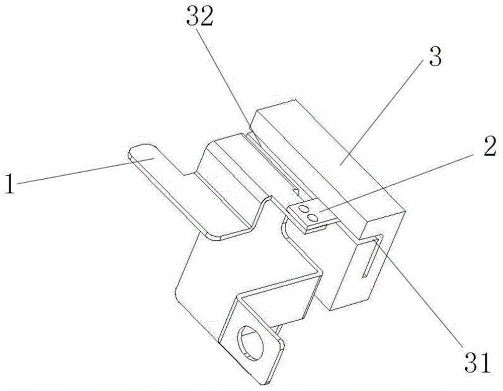
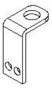
[0040] S1: Connect the lead workpiece 2 (such as figure 2 As shown, it is made of copper or copper alloy, and its shape is composed of two straight plates that are perpendicular to each other and connected together to form an L shape. The welding part of the hole) is positioned on the installation part of the copper bar base 1 through the positioning structure;

[0041]S2: filling brazing material between the lead workpiece 2 and the copper bar substrate 1, and placing the non-welded part of the lead workpiece 2 in the heat dissipation mold 3;

[0042] S3: Using a resistance brazing process, the brazing material is melted by heating the resistance block, so that the lead workpiece 2 and the copper bar base 1 are welded and fixed (such as figure 1 shown);

[0043] The resistance brazing process includes:

[0044] a: Preheat the two resistan...

Embodiment 2

[0061] This embodiment provides a welding method for the conductive layer of a composite copper bar. The difference between this embodiment and Embodiment 1 lies in the specific parameters of the resistance brazing process.

[0062] The resistance brazing process of the present embodiment comprises:

[0063] a: Preheat the two resistance blocks as the upper mold and the lower mold to 100°C higher than the melting temperature of the solder;

[0064] b: Place the installation part of the copper bar base 1 and the welding part of the lead workpiece 2 that have been positioned together by the positioning structure quickly between the two resistance blocks, so that the two resistance blocks are in contact with the installation part and the installation part with a pressure of 0.3MPa The welding parts are bonded;

[0065] c: Continue to pass 800A current to the resistance block, welding for 8s, so that the brazing material is fully melted;

[0066] d: Hold the pressure for 15s aft...

Embodiment 3

[0068] This embodiment provides a welding method for the conductive layer of a composite copper bar. The difference between this embodiment and Embodiment 1 or Embodiment 2 lies in the resistance brazing process.

[0069] The resistance brazing process of the present embodiment comprises:

[0070] a: Preheat the two resistance blocks as the upper mold and the lower mold to 75°C higher than the melting temperature of the solder;

[0071] b: Place the installation part of the copper bar base 1 and the welding part of the lead workpiece 2 that have been positioned together by the positioning structure quickly between the two resistance blocks, so that the two resistance blocks are in contact with the installation part and the installation part with a pressure of 0.25MPa The welding parts are bonded;

[0072] c: Continue to pass 700A current to the resistance block, and weld for 9s to fully melt the brazing material;

[0073] d: Hold the pressure for 12s after disconnecting the ...


PUM


Abstract

The invention relates to a welding method of a composite copper bar conducting layer. A welding part of a lead workpiece is positioned on a mounting part of a copper bar substrate by a positioning structure, so that next welding is facilitated. After positioning, a resistance soldering technology instead of chamfering is adopted, so that the mounting part can be arranged in any position of the copper bar substrate, the lead workpiece can be welded on the mounting part, a complicated composite copper bar product comprising a small forming part structure is obtained, and the welding strength and the connection reliability are improved. A non-welding part of the lead workpiece is placed in a heat-dissipation mold, so that heat of the non-welding part of the lead workpiece conducted by welding can be dissipated by the heat-dissipation mold, the non-welding part of the lead workpiece can avoid softening deformation and hardness and strength reduction due to overheating, the hardness and the strength of the non-welding part are ensured, and torsion resistance of riveting a nut in a non-welding area is ensured. In addition, the invention further relates to a composite copper bar.

Description

technical field [0001] The invention relates to a welding method for a conductive layer of a composite copper bar and the composite copper bar, belonging to the technical field of electronic accessories. Background technique [0002] Composite busbar, also known as composite busbar, bus bar (bus) board, low-inductance busbar, laminated busbar, laminated power busbar, etc., belongs to a multi-layer composite structure connection bar, which is widely used in power electronic equipment An important form of electrical connection is the highway of the power distribution system. The composite busbar adopts a composite structure of conductive materials and insulating materials. Encapsulate single-layer or multi-layer conductors with high dielectric strength materials to form a low-inductance composite structure. Compared with the traditional cable wiring method, the use of composite busbars can provide a safe, fast, clear structure, and highly integrated electrical wiring system....

Claims


Application Information

Patent Timeline
Patent Type & Authority Patents(China)
IPC IPC(8): H01B13/00H01B5/02B23K1/08
Inventor 张胜锰阳林张胜浩
Owner 浙江冠华电气有限公司
Why Eureka
Try Eureka