Sintering furnace with a gas removal device

A technology for exhaust devices and sintering furnaces, which is applied in the field of sintering furnaces and can solve problems such as high fragility and reduced hardness

Inactive Publication Date: 2015-01-28
GKN SINTER METALS GMBH & CO KG
View PDF4 Cites 3 Cited by
  • Summary
  • Abstract
  • Description
  • Claims
  • Application Information

AI Technical Summary

Problems solved by technology

As exemplary undesired consequences, reduced ha

Method used


Image

  • Sintering furnace with a gas removal device
  • Sintering furnace with a gas removal device
  • Sintering furnace with a gas removal device

Examples


Embodiment Construction

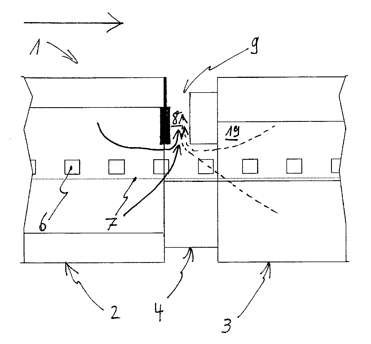
[0062] Figure 1a A sintering furnace 1 in the form of a belt sintering furnace according to the prior art is shown in plan view. In this case, the sintering furnace 1 has a furnace inlet 16 , a first zone 2 configured as a burnout zone, a transition zone 4 , a second zone 3 configured as a sintering zone, a cooling Zone 17 and outlet 18 of the sintering furnace. The green bodies 6 to be sintered lie on a conveying surface 7 which, in the sintering furnace 1 shown, is designed as a sintering belt. In addition, in the sintering furnace 1 shown, muffle walls 19 are arranged on both sides of the conveying surface 7, which are arranged parallel to the boundary line of the conveying surface 7 of the sintering furnace 1 at the provided conveying surface. Viewed in direction, the start of the transition zone 4 extends along the sintering zone 3 to the end of the cooling zone 17 .

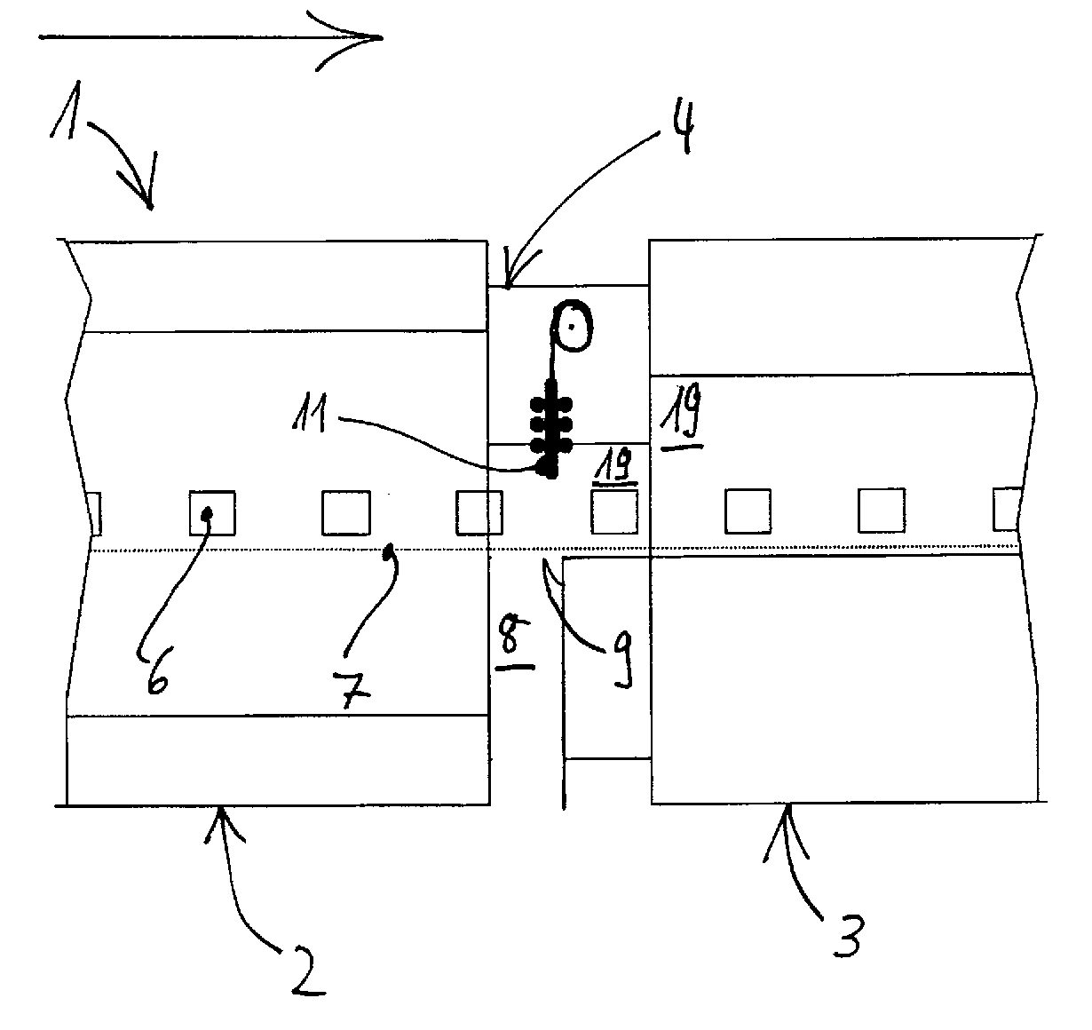
[0063] Figure 1b A sintering furnace 1 constructed as a belt sintering furnace according to the pri...


PUM


Abstract

A sintering furnace with a first zone, in particular a burn-off zone, and a second zone, in particular a sintering zone, and also a transitional zone arranged between the first zone and the second zone. The sintering furnace has at least one transporting mechanism for transporting bodies to be sintered on a transporting area. With this transporting mechanism, the bodies to be sintered can be transported from the first zone and through the transitional zone to the second zone. The sintering furnace also has at least one gas removal device with at least one gas removal device opening. Here, the gas removal device opening is at least partially arranged in the region of the transitional zone. Furthermore, a method by means of which gases can be removed from a sintering furnace is claimed.

Description

technical field [0001] The invention relates to a sintering furnace having an exhaust device which enables an efficient discharge of waste gases from the sintering furnace. Furthermore, a method for removing gases from the sintering furnace is proposed. Background technique [0002] Sintering furnaces through which the bodies to be sintered pass are known. The body to be sintered is first conveyed through a burnout zone in which lubricant and / or wax present in the body to be sintered is removed by burnout at a temperature lower than the sintering temperature ( Wachse). Directly or indirectly following the burnout zone, such sintering furnaces have a so-called sintering zone in which the actual sintering process takes place. An advantage of such a sintering furnace is that it is possible to sinter a large number of green bodies to be sintered in a continuous or substantially continuous process within a short period of time. However, the described sintering furnace has the...

Claims


Application Information

Patent Timeline
IPC IPC(8): F27B21/06F27D17/00C22B1/20
CPCF27D17/001F27B21/06C22F1/18C22F1/183F27D17/004F27D3/12F27D7/00F27D21/00
Inventor E.恩斯特R.阿尔贝特T.舒普
Owner GKN SINTER METALS GMBH & CO KG
Why Eureka
Try Eureka