
Blood flow adjustor for hematodialysis

A flow regulator, hemodialysis technology, applied in dialysis systems, drug devices, other medical devices, etc., can solve problems such as increasing the burden on the heart and jeopardizing the lives of patients, reducing the degree of surgical damage, avoiding heart overload, and reducing heart disease. fading effect

Inactive Publication Date: 2015-02-04
宋会中
View PDF6 Cites 5 Cited by
  • Summary
  • Abstract
  • Description
  • Claims
  • Application Information

AI Technical Summary

Problems solved by technology

[0002] Now in hemodialysis, arteriovenous fistula is often made, because the high-pressure blood in the artery flows directly into the vein through the fistula, and because the blood flow pressure in the artery is greater than the venous blood pressure, in order to reconcile the pressure difference, the vein itself will expand. This leads to a vicious circle; a large amount of blood returns to the heart, which greatly increases the burden on the heart. Excessive blood flows back to the heart through the internal fistula for a long time, causing heart failure and endangering the life of the patient.

Method used


Image

  • Blood flow adjustor for hematodialysis
  • Blood flow adjustor for hematodialysis
  • Blood flow adjustor for hematodialysis

Examples


Embodiment 1

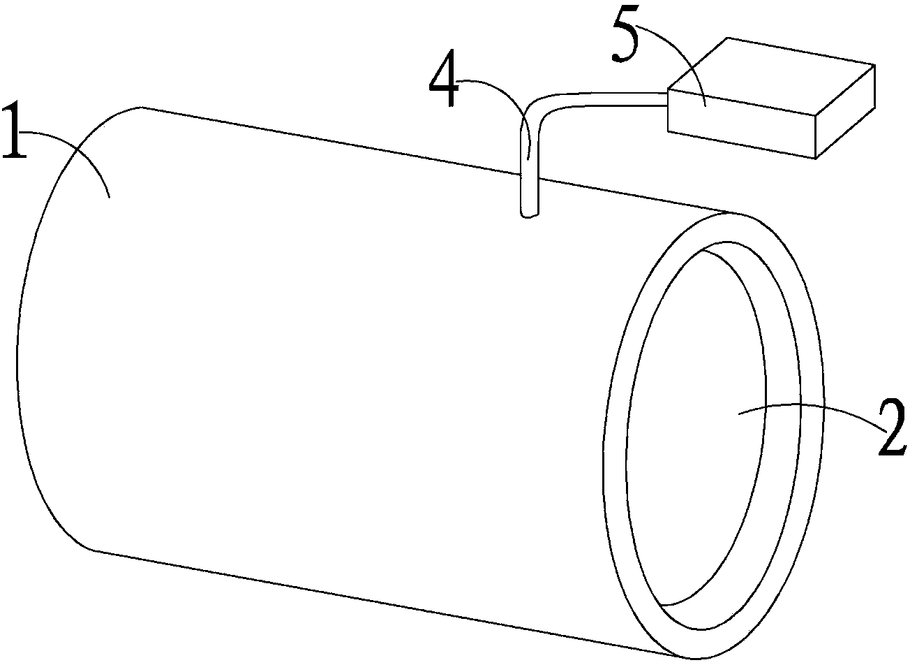
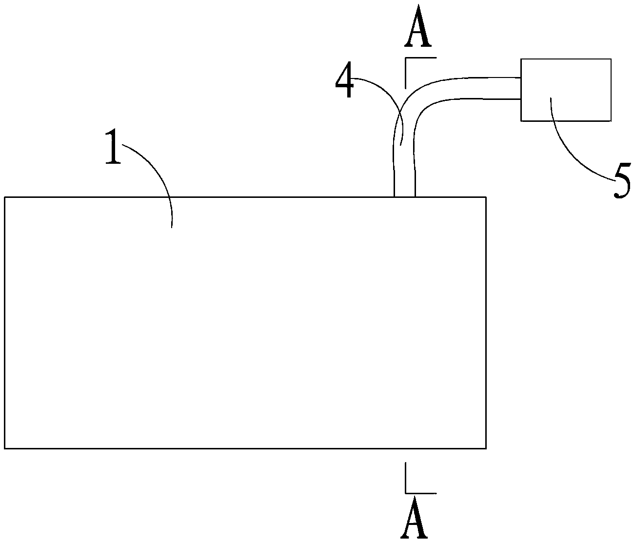
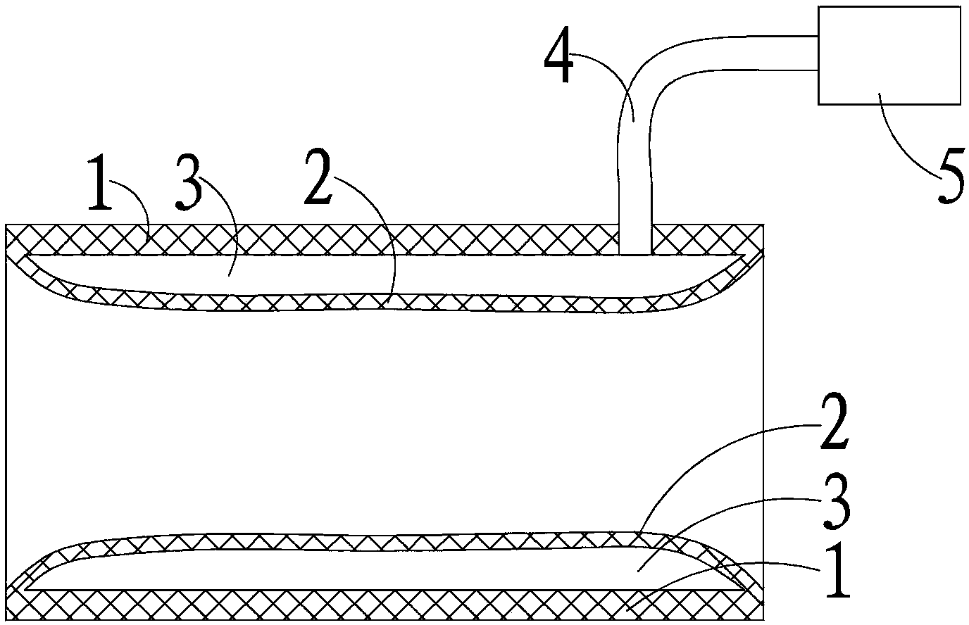
[0032] as attached Figures 1 to 4 As shown, the present invention includes: a base wall 1 and an expansion bag 2 laid on one side of the base wall 1, the expansion bag 2 and the base wall 1 are formed with an expansion cavity 3, and the expansion cavity 3 passes through a catheter 4 and a self-sealing device 5 connect. The blood flow regulator is pre-installed on the vein side of the arteriovenous fistula, and gas or liquid is filled into the inflation cavity 3 through the catheter 4, and the catheter 4 is sealed by the self-sealing device 5, which is embedded under the skin, and the expansion bag 2 can restrain the vein Return blood flow, control the required return flow, and avoid heart overload.

[0033] The conduit 4 is arranged on the base wall 1 and communicates with the expansion chamber 3 through the base wall 1 . The catheter 4 communicates with the expansion cavity 3 through the base wall 1, and the expansion bag 2 is close to the outer wall of the venous blood ve...

Embodiment 2

[0042] as attached Figures 5 to 7 As shown, the difference from Embodiment 1 is that the base wall 1 is plate-shaped, the base wall 1 is plate-shaped, the edge of the expansion bag 2 is connected to the base wall 1, and the corresponding two ends of the base wall 1 are provided with connecting mechanisms The connection mechanism includes a lock tongue 6 fixed at one end of the base wall 1 and a lock 7 fixed at the other end of the base wall 1 . The plate-shaped blood flow regulator can be curled and wrapped around the outside of the venous blood vessel, which can limit the blood flow without cutting off the blood vessel, and reduce the degree of surgical damage during installation. The two ends of the plate-shaped blood flow regulator are provided with matching locks, so that the plate-shaped regulator can be wrapped and fixed on the venous blood vessel, and the fixing is convenient and reliable.

[0043] The self-styled device 5 is an infusion port or a micro-infusion pump ...


PUM

PropertyMeasurementUnit
Diameteraaaaaaaaaa

Abstract

The invention relates to a blood flow adjustor for hematodialysis. The blood flow adjustor comprises a basal wall and an expansion capsule covering one side of the basal wall; the expansion capsule and the basal wall are provided with an expansion chamber; the expansion chamber is connected with a self-sealing device through a catheter; the blood flow adjustor is arranged on the vein side of internal arteriovenous fistula in advance, gas or liquid is injected into the expansion chamber through the catheter, the catheter is sealed by the self-sealing device, the catheter is implanted under the skin, the expansion capsule expands to restrain blood flow of venous return, the required return quantity is controlled, the overload of the heart is avoided, and heart failure of a hematodialysis patient is effectively reduced.

Description

technical field [0001] The invention relates to a device for hemodialysis, in particular to a blood flow regulator for hemodialysis. technical background [0002] Now in hemodialysis, arteriovenous fistula is often made, because the high-pressure blood in the artery flows directly into the vein through the fistula, and because the blood flow pressure in the artery is greater than the venous blood pressure, the vein itself will expand in order to reconcile this pressure difference. This leads to a vicious cycle; a large amount of blood returns to the heart, which greatly increases the burden on the heart. Excessive blood flows back to the heart through the internal fistula for a long time, causing heart failure and endangering the life of the patient. [0003] In the initial stage of making the internal fistula, the blood flow through the internal fistula is set to be 500ml / min; after the completion of the production, the veins begin to become larger, and the flow of the inte...

Claims


Application Information

Patent Timeline
IPC IPC(8): A61M1/14
CPCA61M1/14A61M2202/0021A61M2202/0413A61M2205/3337A61M2210/005
Inventor 宋会中
Owner 宋会中
Learn More