
Fixture for gear shaping on thin-wall outer gear ring

A gear ring and thin-walled technology, which is applied in the field of thin-walled outer gear ring gear shaping fixtures, can solve the problems that the gear ring is difficult to meet the matching requirements of high-end cars, and the positioning accuracy of the expansion mandrel fixture cannot be very high, so as to achieve small deformation, Reasonable axial locking structure and simple positioning structure

Inactive Publication Date: 2015-02-04
JIANGSU PACIFIC PRECISION FORGING +1
View PDF7 Cites 5 Cited by
  • Summary
  • Abstract
  • Description
  • Claims
  • Application Information

AI Technical Summary

Problems solved by technology

However, the positioning of the expansion mandrel fixture is mainly achieved by the elastic deformation of the built-in expansion sleeve. The positioning accuracy of this floating positioning structure is affected by factors such as the uniformity of the opening groove on the expansion sleeve wall, the material of the expansion sleeve, and the quality of heat treatment.
Therefore, the positioning accuracy of the expansion mandrel fixture cannot be very high, and the gear ring processed by the expansion mandrel fixture is difficult to meet the matching requirements of high-end cars

Method used


Image

  • Fixture for gear shaping on thin-wall outer gear ring
  • Fixture for gear shaping on thin-wall outer gear ring
  • Fixture for gear shaping on thin-wall outer gear ring

Examples


Embodiment Construction

[0013] The present invention will be further described below according to the accompanying drawings and in conjunction with the embodiments.

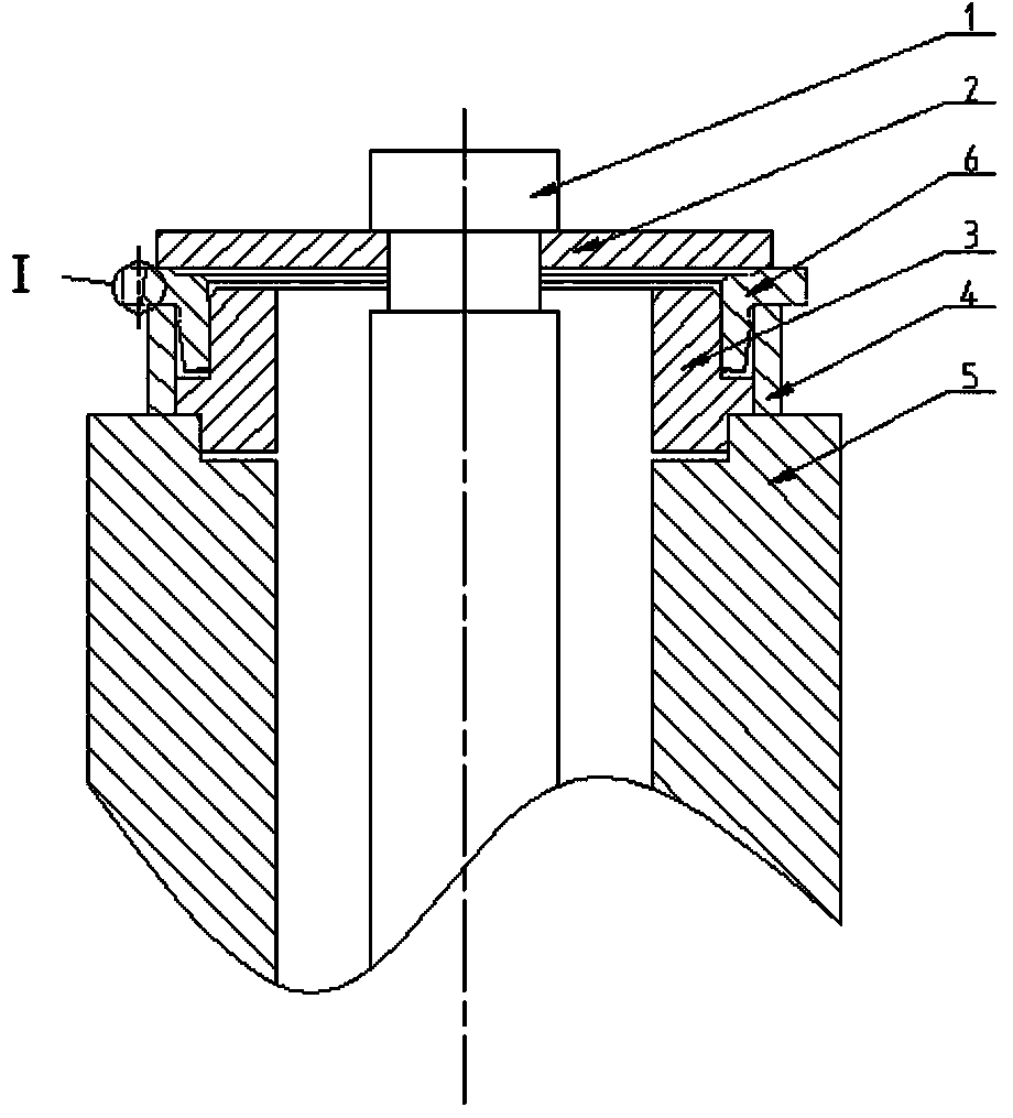
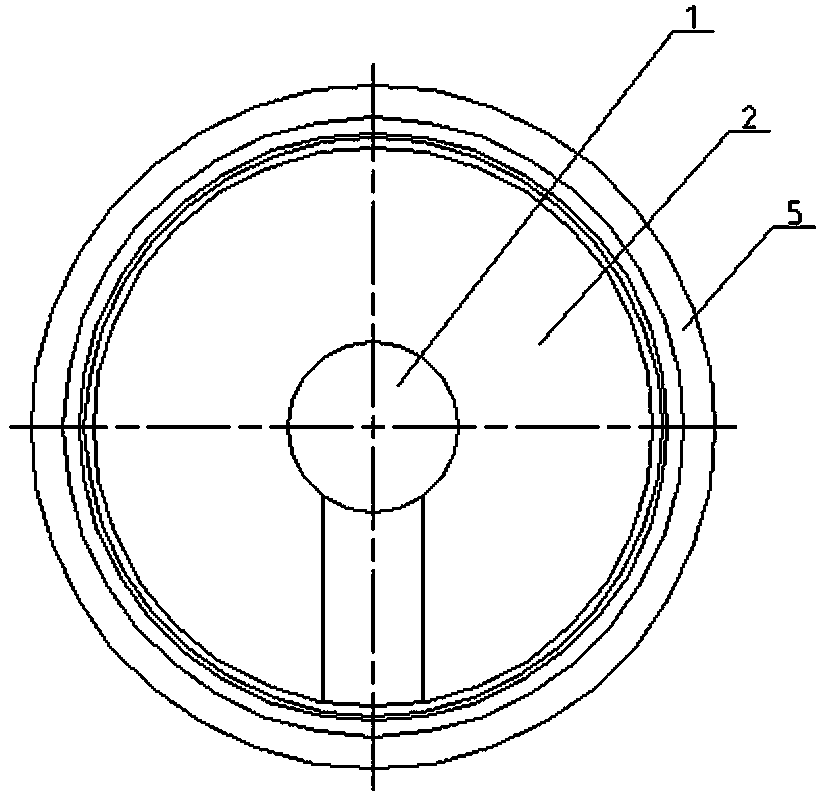
[0014] figure 1 The shown thin-walled external gear ring gear shaping fixture is composed of a tie rod 1, a washer 2, a shaft seat 3, a shaft sleeve 4 and a base 5, and the fixture is positioned and installed on the gear shaping machine table. The base 5 is the main component of the clamp and is used to carry other supporting components. The upright base 5 is a hollow shaft segment, and the upward end face is provided with a concave stop, which is used for positioning and installing the shaft seat 3 . The shaft seat 3 is a multi-section shaft member. The two shaft segments on the upper and lower sides of the outer convex shoulder are coaxial. 5 spins. The shaft segment located in the previous section is used for the positioning of the workpiece 6 , and its outer diameter is matched with the inner hole of the workpiece 6 in a clearanc...


PUM


Abstract

The invention discloses a fixture for gear shaping on a thin-wall outer gear ring. The fixture jointly consists of a pull rod, a gasket, a shaft seat, a shaft sleeve and a substrate, wherein the end face facing upwards of the substrate is provided with a concave spigot for installing the shaft seat in a positioning manner; the pull rod penetrates the inner bore of the substrate, and an annular groove is formed in the outer wall of the upper exposed rod end; the gasket is assembled in the groove to form a linkage structure; the shaft seat of the fixture disclosed by the invention is a multi-section shaft component, two sections of shaft segments located above and below a convex circular bead are coaxial, and the external diameter of the previous section of shaft segment is in clearance fit with the inner bore of a workpiece to form a positioning structure; the shaft sleeve directly covers the shaft sleeve, the shaft sleeve is located between the opposite end faces of the substrate and the workpiece, the workpiece is axially supported by the shaft sleeve, and the workpiece is axially locked by the gasket moving down along with the pull rod. According to the fixture disclosed by the invention, aiming at the problems that the rigidity of the thin-wall gear ring is insufficient and the deformation of the thin wall can be easily caused by the gear shaping, the radial positioning and axial locking structure is adopted, so that the thin wall of the workpiece is neither subjected to the action of the radial force nor subjected to the action of the axial force, and therefore the goals that machining deformation is reduced and the machining accuracy is improved are achieved.

Description

technical field [0001] The present invention relates to a machining jig, in particular, the present invention relates to a jig for gear shaping, especially a gear shaping jig for thin-walled external gear ring. Background technique [0002] Automobile synchronizer ring gear is a typical thin-walled transmission part. The rigidity of this thin-walled transmission part is relatively weak, and it is inevitable that it will not deform during the forming process. The positioning and clamping structure of the ring gear in the fixture are related to the impact force of plunging. In order to reduce machining deformation and improve manufacturing quality, expanding mandrel clamps are commonly used in this industry for gear ring positioning and gear shaping. The expansion mandrel clamp is a clamp with an integrated structure of positioning and clamping. Its structure is relatively simple, the clamping is easy, the positioning is reliable, and it can achieve barrier-free gear shaping....

Claims


Application Information

Patent Timeline
Patent Type & Authority Applications(China)
IPC IPC(8): B23F23/06
Inventor 苟文星秦钧赵军华
Owner JIANGSU PACIFIC PRECISION FORGING
Learn More