Segmenting power supply distributed protection system for electrified railway traction network

A technology for electrified railways and segmented power supply, applied in power lines, electrical components, electric vehicle charging technology, etc., can solve the problem of data synchronization acquisition and transmission fault information centralized processing real-time difficulties, increased number of segments, affecting practicability, etc. problems, to achieve the effect of reducing the scope of power outages, improving reliability, and facilitating implementation

Active Publication Date: 2015-02-04
SOUTHWEST JIAOTONG UNIV
View PDF5 Cites 23 Cited by
  • Summary
  • Abstract
  • Description
  • Claims
  • Application Information

AI Technical Summary

Problems solved by technology

Since the current traction substations are connected to the power system with commutation phases and use out-of-phase power supply, the traction network is not connected to each other and the number of segments is small. This method is convenient and effective; but when the same-phase power supply is implemented, the traction network will be connected. The number of segments is greatly increased, and the real-time performance of synchronous data acquisition and transmission and centralized processing of fault information becomes difficult or even impossible, which will greatly affect the practicability of the method

Method used


Image

  • Segmenting power supply distributed protection system for electrified railway traction network
  • Segmenting power supply distributed protection system for electrified railway traction network
  • Segmenting power supply distributed protection system for electrified railway traction network

Examples


Embodiment Construction

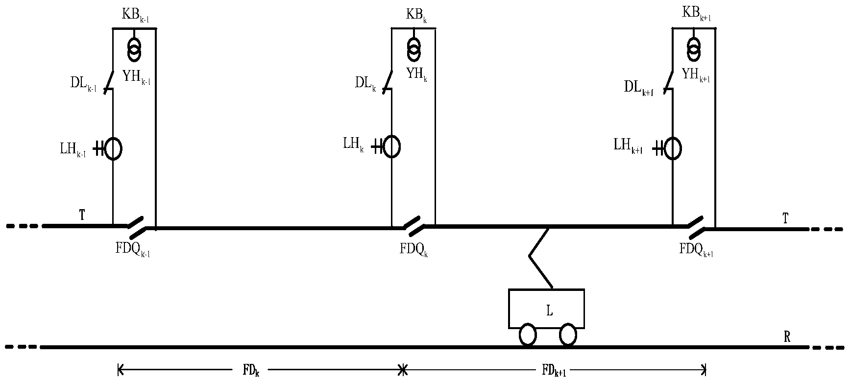
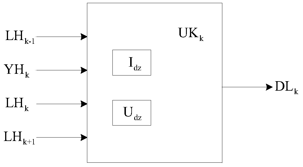
[0020] figure 1 Shown, a kind of specific embodiment of the present invention is: corresponding to the interval (about 10km) of railway, the catenary in the electrified railway traction network is divided into several subsections FD, and the catenary sectionalizer is set up in subsection FDQ and switching station KB; switching station KB includes circuit breaker DL, current transformer LH, voltage transformer YH and measurement and control unit CK; circuit breaker DL and current transformer LH connected in series with it are connected across the catenary sectionalizer On the FDQ, the sectionalizer FDQ is connected in series in the catenary, enabling the train to pass through without interruption; the circuit breaker DL is usually in the closed state; the voltage transformer YH is connected to the catenary T in parallel; the current transformers are of the same type, The transformation ratio is the same, and the models and transformation ratios of each voltage transformer are t...


PUM


Abstract

The invention discloses a segmenting power supply distributed protection system for an electrified railway traction network. An overhead line in the electrified railway traction network is divided into a plurality of sections by corresponding to the intervals of a railway, sectionalizers and switching stations are additionally arranged on segmentation positions; each switching station comprises a breaker, a current transformer, a voltage transformer and a measurement and control unit; the breaker is always under a switching-on state; the secondary side of the voltage transformer and the secondary side of the current transformer of the switching station, the secondary side of the current transformer of the left adjacent switching station and the secondary side of the current transformer of the right adjacent switching station are connected with the input end of each measurement and control unit; the output end of each measurement and control unit is connected with the control end of the breaker of each switching station; each measurement and control unit is connected with a traction substation or control center via a transmission network. The invention forms a segmenting distributed protection method for the traction network. Compared with a centralized protection method, the segmenting distributed protection method has the characteristics that the instantaneity is not affected by the segmentation amount of the traction network. The relevant device disclosed by the invention has the advantages of small investment, convenience in implementation and convenience in new line adoption and old line modification.

Description

technical field [0001] The invention belongs to the technical field of AC electrified railway traction network protection, and in particular relates to a segmental power supply protection method and device for electrified railway traction network. Background technique [0002] The traction power supply system of electrified railway is composed of traction substation and traction network. The traction network of the direct power supply method is composed of catenary, track and ground. In order to improve the power supply capacity of the traction network, reduce the power supply voltage and energy loss, and maintain the relative independence of the uplink and downlink catenary, the uplink and downlink catenary are usually connected in parallel at the end of the double-track railway traction network (division office). However, when a fault occurs in the upper (lower) catenary, the upper (lower) feeder and the partition substation of the traction substation will be tripped, so ...

Claims


Application Information

Patent Timeline
Patent Type & Authority Applications(China)
IPC IPC(8): B60M3/04
CPCB60M3/04B60L3/04B60M3/02H02H7/267Y02T90/16G01R31/086
Inventor 李群湛黄彦全易东李亚楠
Owner SOUTHWEST JIAOTONG UNIV
Why Eureka
Try Eureka