Power distribution cabinet lifting device

A technology for lifting devices and power distribution cabinets, which is applied in the direction of lifting devices, switch devices, electrical components, etc., and can solve problems such as time-consuming and labor-intensive, potential safety hazards, and easy sliding of power distribution cabinets

Inactive Publication Date: 2015-02-04
SUZHOU SHIJIJINGYUAN OPTIC
View PDF7 Cites 18 Cited by
  • Summary
  • Abstract
  • Description
  • Claims
  • Application Information

AI Technical Summary

Problems solved by technology

[0002] In the processing and assembly process of high-voltage power distribution cabinets, because many electrical components are high-voltage equipment, the weight and volume are relatively large. When lifting, due to the limited space of the cabinet, it is impossible to allow multiple people to lift it reasonably. Therefore, a lifting device is urgently needed to lift such large electrical components, and the components are placed on the lifting device. The automatic lifting of the device does not require manpower, which saves time and effort, and eliminates potential safety hazards. The application number is CN201110373704. The left end of the mounting plate is provided with a cylinder body, the cylinder body is provided with a cylinder fixing guide rail, the cylinder body is provided with an L-shaped lifting platform, the upper part of the cylinder body is provided with a piston rod, and the L-shaped lifting platform is provided with a clamping carrier. There is a hydraulic pump on one side, and a manual hydraulic rod on the hydraulic pump. You can use the lifting device of the power distribution cabinet to clamp the heavy electrical components and lift them up and down according to the required installation position, avoiding manual lifting. The assembly of the power distribution cabinet provides convenience, and has the characteristics of simple structure, time-saving, labor-saving and safety. However, this type of power distribution cabinet lifting device can only send the power distribution cabinet to the required height. It is often necessary to carry it manually. Due to the heavy weight of the general power distribution cabinet, it is very inconvenient to carry, time-consuming and laborious, and there is no limit device, and the power distribution cabinet is prone to slide on the lifting platform.

Method used


Image

  • Power distribution cabinet lifting device
  • Power distribution cabinet lifting device
  • Power distribution cabinet lifting device

Examples


Embodiment Construction

[0014] In order to make the technical means, creative features, goals and effects achieved by the present invention easy to understand, the present invention will be further described below in conjunction with specific embodiments.

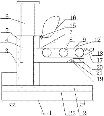
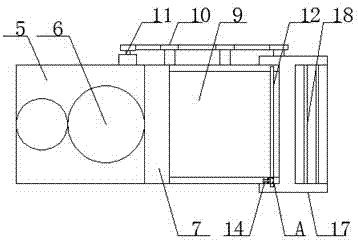
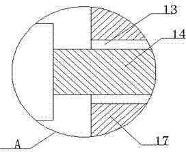
[0015] Such as figure 1 with figure 2 As shown, a lifting device for a power distribution cabinet includes a transport trolley 1, a load mounting plate 2 is provided on the transport trolley 1, a cylinder body 3 is provided at the left end of the load mounting plate 2, and a cylinder fixing guide rail 4 is provided inside the cylinder body 3. The cylinder body 3 is provided with an L-shaped lifting platform 5, the upper part of the cylinder body 3 is provided with a piston rod 6, and the L-shaped lifting platform 5 is provided with a loading platform 7, and the loading platform 7 is provided with 3-5 pulleys 8 , the pulley 8 is provided with a conveyor belt 9, one end of the pulley 8 is connected to a sprocket 10, the sprocket 10 is connected t...


PUM


Abstract

The invention discloses a power distribution cabinet lifting device and relates to the technical field of power distribution cabinet equipment. The power distribution cabinet lifting device comprises a transport trolley, wherein a load bearing installation plate is arranged on the transport trolley, a cylinder is arranged at the left end of the load bearing installation plate, cylinder fixing guide rails are arranged in the cylinder, an L-shaped lifting platform is arranged on the cylinder, a piston rod is arranged at the upper part of the cylinder, an object carrying platform is arranged on the L-shaped lifting platform, 3-5 belt rollers are arranged on the object carrying platform, a conveying belt is arranged on the belt rollers, certain ends of the belt rollers are connected with a sprocket, the sprocket is connected with a driving motor, a limiting plate is arranged on the right side of the object carrying platform, one end of the limiting plate is hinged onto the object carrying platform, and the other end of the limiting plate is provided with a hole and is fixed on the object carrying platform through a bolt. The lifting device has the advantages that the power distribution cabinet is convenient to transport, the time and labor are saved and the safety is high.

Description

technical field [0001] The invention relates to the technical field of power distribution cabinet equipment, in particular to a lifting device for a power distribution cabinet. Background technique [0002] In the processing and assembly process of high-voltage power distribution cabinets, because many electrical components are high-voltage equipment, the weight and volume are relatively large. When lifting, due to the limited space of the cabinet, it is impossible to allow multiple people to lift it reasonably. Therefore, a lifting device is urgently needed to lift such large electrical components, and the components are placed on the lifting device. The automatic lifting of the device does not require manpower, which saves time and effort, and eliminates potential safety hazards. The application number is CN201110373704. The left end of the mounting plate is provided with a cylinder body, the cylinder body is provided with a cylinder fixing guide rail, the cylinder body i...

Claims


Application Information

Patent Timeline
Patent Type & Authority Applications(China)
IPC IPC(8): B66F9/19B66F9/18B66F9/12H02B3/00
CPCB66F9/19B66F9/127B66F9/18H02B3/00
Inventor 钱玉明
Owner SUZHOU SHIJIJINGYUAN OPTIC
Why Eureka
Try Eureka