Venting plug of automobile transmission

A technology for automotive transmissions and exhaust plugs, applied to components with teeth, transmission parts, belts/chains/gears, etc., can solve problems such as leakage of exhaust plugs, increase flow, prevent leakage, and improve efficiency effect

Inactive Publication Date: 2015-02-04
SICHUAN YOUKE COMM TECH
View PDF8 Cites 9 Cited by
  • Summary
  • Abstract
  • Description
  • Claims
  • Application Information

AI Technical Summary

Problems solved by technology

[0007] In order to solve the problem of leakage of the exhaust plug of the automobile transmission under the action of high temperature and centrifugal force, the present invention provides an exhaust plug of the automobile transmission, which can prevent the leakage of lubricating oil

Method used


Image

  • Venting plug of automobile transmission
  • Venting plug of automobile transmission
  • Venting plug of automobile transmission

Examples


Embodiment 1

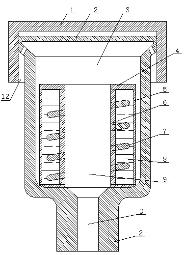
[0033] The exhaust plug of the automobile transmission of the present embodiment comprises a plug cover and a plug body with an exhaust cavity, the plug cover is sleeved on the plug body, an annular air outlet is formed between the plug cover inner wall and the plug outer wall, and the exhaust There is a ventilation pipe in the cavity, the ventilation pipe includes an outer shell and an inner shell with a cavity, the outer shell is sleeved on the periphery of the inner shell and connected together through an end cover to form a sealed cooling cavity, and the cooling cavity is filled with cooling liquid; A spiral deflector is arranged on the outer wall of the inner shell.

Embodiment 2

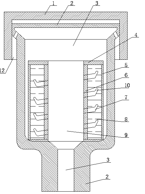
[0035] The exhaust plug of the automobile transmission of the present embodiment comprises a plug cover and a plug body with an exhaust cavity, the plug cover is sleeved on the plug body, an annular air outlet is formed between the plug cover inner wall and the plug outer wall, and the exhaust There is a ventilation pipe in the cavity, the ventilation pipe includes an outer shell and an inner shell with a cavity, the outer shell is sleeved on the periphery of the inner shell and connected together through an end cover to form a sealed cooling cavity, and the cooling cavity is filled with cooling liquid; The outer wall of the inner shell is provided with a spiral deflector; the outer edge of the spiral deflector is provided with a baffle arranged obliquely upward.

Embodiment 3

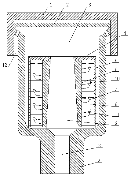
[0037] The exhaust plug of the automobile transmission of the present embodiment comprises a plug cover and a plug body with an exhaust cavity, the plug cover is sleeved on the plug body, an annular air outlet is formed between the plug cover inner wall and the plug outer wall, and the exhaust There is a ventilation pipe in the cavity, the ventilation pipe includes an outer shell and an inner shell with a cavity, the outer shell is sleeved on the periphery of the inner shell and connected together through an end cover to form a sealed cooling cavity, and the cooling cavity is filled with cooling liquid; The outer wall of the inner shell is provided with a spiral deflector; the outer edge of the spiral deflector is provided with an obliquely upward baffle; the baffle is provided with a through hole to facilitate the flow of the cooling liquid, and the through hole is obliquely upwardly opened on the bezel.


PUM


Abstract

The invention discloses a venting plug of an automobile transmission, and aims to solve the problem of leakage of the venting plug of the conventional automobile transmission under the actions of high temperature and centrifugal force. The venting plug comprises a plug cover and a plug body provided with a venting cavity, wherein the plug cover is arranged on the plug body in a sleeving way; an annular air outlet is formed between the inner wall of the plug cover and the outer wall of the plug body; a ventilation pipe is arranged in the venting cavity; the ventilation pipe comprises an outer shell and an inner shell provided with a cavity; the outer shell is arranged on the periphery of the inner shell in a sleeving way, and is connected with the inner shell through an end cover, thereby forming a sealed cooling cavity; cooling liquid is injected into the cooling cavity; the outer wall of the inner shell is provided with a helical guide plate. By adopting the venting plug, leakage of lubricating oil can be prevented.

Description

technical field [0001] The invention relates to a transmission of an automobile engine, in particular to an exhaust plug of an automobile transmission. Background technique [0002] At present, the exhaust plug device of the automobile engine is installed on the transmission shift box, which is located at the highest position of the transmission. The internal cavity of the transmission assembly is kept consistent with the external pressure through the exhaust hole to avoid the pressure increase of the gear lubricating oil. When the car is running, the gears of the transmission will rub against each other to generate a lot of heat, which will raise the temperature of the transmission lubricating oil to 70-80°C. The lubricating oil attached to the surface of the gear is thrown out from the tangential direction due to the centrifugal force generated by the high-speed rotation of the gear. Since the inner cavity of the exhaust plug does not have any blocking medium, part of the ...

Claims


Application Information

Patent Timeline
Patent Type & Authority Applications(China)
IPC IPC(8): F16H57/027F16H57/04
CPCF16H57/027F16H57/0413F16H2700/00
Inventor 方远兵郑俊杰唐福生
Owner SICHUAN YOUKE COMM TECH
Why Eureka
Try Eureka