Rotor for rotating electric machine, rotating electric machine, and method for manufacturing rotor for rotating electric machine

A technology for rotating electrical machines and rotors, applied in the manufacture of motor generators, stator/rotor bodies, and electric components, etc., can solve problems such as hindering labor saving, improving productivity, and complicated operation time.

Inactive Publication Date: 2015-02-04
MITSUBISHI ELECTRIC CORP
View PDF8 Cites 11 Cited by
  • Summary
  • Abstract
  • Description
  • Claims
  • Application Information

AI Technical Summary

Problems solved by technology

[0006] In this assembly process, there is a problem that the positioning and fixing of each permanent magnet and each laminated core member becomes complicated and the working time increases.
[0007] In addition, there is a problem that the operator's proficiency is required, which hinders labor saving and productivity improvement.

Method used


Image

  • Rotor for rotating electric machine, rotating electric machine, and method for manufacturing rotor for rotating electric machine
  • Rotor for rotating electric machine, rotating electric machine, and method for manufacturing rotor for rotating electric machine
  • Rotor for rotating electric machine, rotating electric machine, and method for manufacturing rotor for rotating electric machine

Examples


Embodiment approach 1

[0087] Hereinafter, the rotor of the rotating electric machine according to Embodiment 1 of the present invention will be described with reference to the drawings.

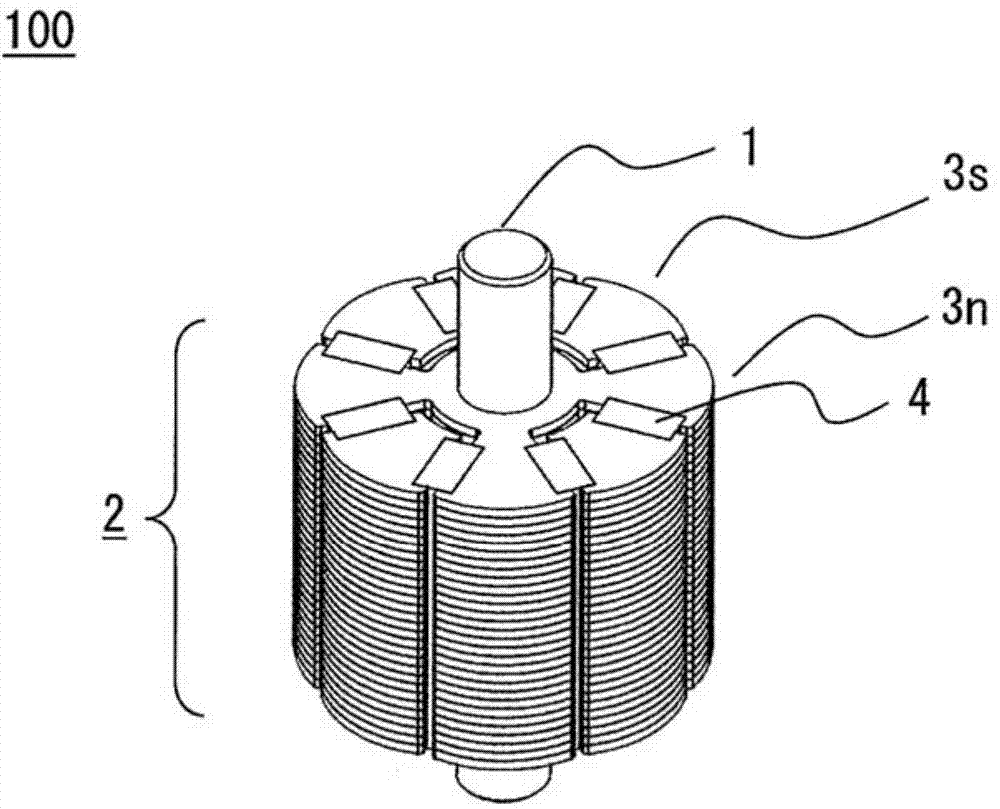
[0088] figure 1 It is an oblique view of the rotor 100.

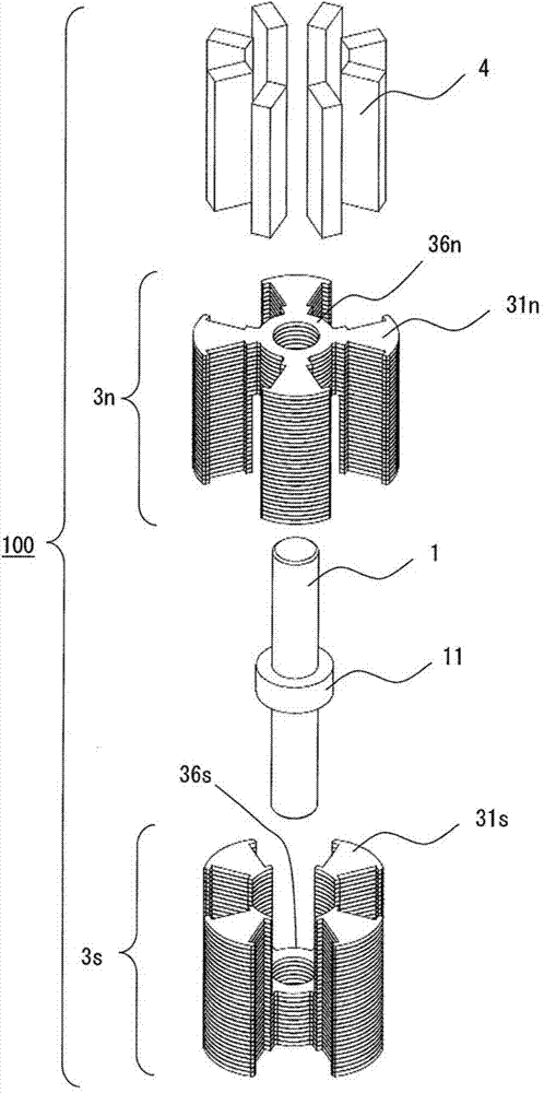
[0089] figure 2 It is an exploded perspective view of the rotor 100.

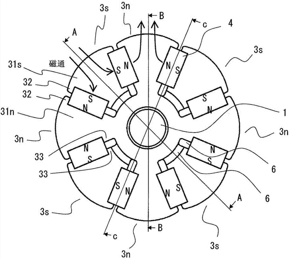
[0090] image 3 It is a top view of the rotor 100.

[0091] Figure 39 It is a cross-sectional view of the electric motor 50 (rotating electric machine).

[0092] In such Figure 39 The rotor 100 used in the motor 50 (rotating electric machine) shown is an N-pole integrated laminated core 3n and an S-pole integrated laminated core 3s, a non-magnetic rotating shaft 1, and the circumference of the rotating shaft 1 is alternately magnetized in the circumferential direction A plurality of permanent magnets 4 (first permanent magnets) are combined and configured.

[0093] Hereinafter, in this specification, the N-pole integrated laminated core 3n and the S-pole integrated laminated core 3s are desig...

Embodiment approach 2

[0142] Hereinafter, with reference to the drawings, the rotor of the rotating electric machine according to the second embodiment of the invention of the present application will be described centering on the parts different from the first embodiment.

[0143] Components with the same reference numerals as those described in the first embodiment basically indicate the same components

[0144] Picture 10 It is a cross-sectional view of the rotor 200.

[0145] The rotor 200 is a non-magnetic rotating shaft 201 with a non-magnetic collar 211 inserted as an independent member to constitute a member having the same shape as the rotating shaft 1 of the first embodiment.

[0146] By forming the structure as described above, it is possible to reduce the amount of expensive non-magnetic material used compared to Embodiment 1.

[0147] In addition, it is possible to adopt an assembly sequence in which the N-pole integrated laminated core 3n, the non-magnetic collar 211, and the S-pole integrated...

Embodiment approach 3

[0149] Hereinafter, with reference to the drawings, the rotor of the rotating electric machine according to the third embodiment of the invention of the present application will be described centering on the different parts from the second embodiment.

[0150] Components with the same reference numerals as those described in Embodiment 1 or 2 basically indicate the same components.

[0151] Picture 11 It is a cross-sectional view of the rotor 300.

[0152] Picture 12 Yes Picture 11 Enlarged view of the main part.

[0153] In the rotor 300, a cylindrical permanent magnet 311 (second permanent magnet) is inserted into a non-magnetic rotating shaft 201 to constitute a rotor having the same shape as the rotating shaft 1 of the first embodiment.

[0154] Such as Picture 12 As shown, the permanent magnet 311 is magnetized so that the N pole is arranged on the side in contact with the laminated ring-shaped connecting portion 36n of the N-pole integrated laminated core 3n, and the N pole is...


PUM


Abstract

Provided is a rotor for a rotating electric machine which includes: an N pole integrally-stacked core in which a plurality of stacked tooth portions that contact with N pole side portions of adjacent ones of first permanent magnets are integrated with each other; and an S pole integrally-stacked core in which a plurality of stacked tooth portions that contact with S pole side portions of adjacent ones of the first permanent magnets are integrated with each other, and in which the N pole integrally-stacked core and the S pole integrally-stacked core are disposed around a rotation shaft having a non-magnetic outer circumferential surface so as to dispose the first permanent magnets and a gap therebetween.

Description

Technical field [0001] The present invention relates to a rotor of a rotating electric machine, a rotating electric machine, and a method of manufacturing the rotor of the rotating electric machine. Background technique [0002] At present, as one of the methods to reduce the size and performance of the rotor of a motor, a technique for effectively utilizing the magnetic field of the permanent magnet by using a rotor in which a plurality of permanent magnets and a plurality of laminated The plurality of permanent magnets are alternately magnetized in the circumferential direction around the rotating shaft, and the plurality of laminated core members form magnetic poles between the permanent magnets. [0003] In such a rotor, the laminated core member is a laminated body using a substantially fan-shaped thin plate chip made of a magnetic material such as a silicon steel plate, and is formed by integrally joining them by a riveting work of a press. [0004] In this case, each permanen...

Claims


Application Information

Patent Timeline
Patent Type & Authority Applications(China)
IPC IPC(8): H02K1/22H02K1/27H02K15/03
CPCH02K1/27H02K15/03H02K1/2773Y10T29/49012H02K1/22
Inventor 冈启一郎秋田裕之
Owner MITSUBISHI ELECTRIC CORP
Why Eureka
Try Eureka