
Brush system for an electric motor

A technology of electric motors and brushes, applied in the direction of electric components, electromechanical devices, electrical components, etc., can solve the problem of increasing the manufacturing cost and assembly cost of the brush system, the difficulty in positioning the components of the cable-guided brush system, and the unfavorable efficiency of conductor traces And save space and other issues, to achieve the effect of optimizing electromagnetic compatibility, simplifying maintenance or repair, and low-cost protection

Active Publication Date: 2015-02-04
BROSE FAHRZEUGTEILE GMBH & CO KG HALLSTADT (DE)
View PDF7 Cites 2 Cited by
  • Summary
  • Abstract
  • Description
  • Claims
  • Application Information

AI Technical Summary

Problems solved by technology

[0005] In the known brush system, one connection tongue (Anschlusslasche) of a flat resistor is arranged on the narrow side of the half-ring of the resistor housing, thereby disadvantageously making efficient and space-saving cabling of the conductor tracks Guiding and positioning of brush system components on the base body becomes difficult
This disadvantageously increases the manufacturing and assembly costs of such brush systems

Method used


Image

  • Brush system for an electric motor
  • Brush system for an electric motor
  • Brush system for an electric motor

Examples


Embodiment Construction

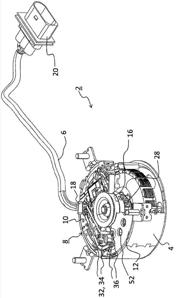
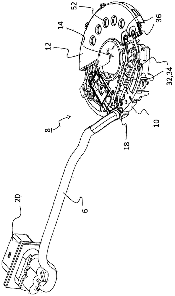
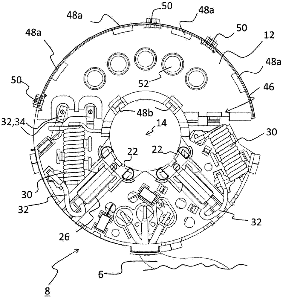
[0028] figure 1 Shown is an electric drive 2 with a motor housing 4 made of metal and with electrical cables 6 for connection to conductor lines and a brush system 8 . The brush system 8 is substantially circular and is formed on one side by a semi-circular carrier plate 10 of non-conductive material, in particular plastic, and on the other side by a likewise semi-circular metallic resistor. The device housing 12 is formed. The brush system 8 has a central recess 14 in which the electric motor 16 is arranged in the assembled state. In the assembled state, the brush system 8 is coupled to the motor housing 4 . The cable 6 has a plug connection 18 to the drive 2 on the motor side and a plug connection 20 on the conductor line side.

[0029] exist figure 2 and image 3 The brush system 8 is shown in more detail in . On the underside ( image 3 ), two carbon brushes 22 are arranged as sliding contacts on the periphery of the not-shown rotor of the electric motor 16 . As s...


PUM


Abstract

The invention relates to a brush system (8) for an electric motor (16), comprising a substantially semi-annular resistor housing (12) into which an electric flat resistor (38) is introduced, two resistor terminals (36) which protrude from the resistor housing (12) and can be coupled in an electrically conducting manner to a conductor path (32) of the electric motor (16), and a substantially semi-circular support plate (10) that includes two bus bars (34) to electroconductively couple the conductor path (32) to the terminals (36) and to two brush elements (22). The two terminals (36) are arranged on the same narrow side of the resistor housing (12).

Description

technical field [0001] The invention relates to a brush system for an electric motor comprising a substantially semi-annular resistor housing with a flat resistor inserted therein, two brushes protruding from the resistor housing Resistor connectors that can be electrically conductively connected to the conductor lines of the electric motor and a substantially semicircular carrier plate with two busbars for electrically conductively connecting the conductor lines to the connectors and two busbars for the Brush element of the sliding contact of the commutator of an electric motor connected to the interference suppression element. Furthermore, the invention relates to an electric motor with such a brush system. Background technique [0002] Such an electric motor, in particular a so-called commutator motor, comprises a stator and a rotor arranged on the motor shaft, which is moved within the stator by means of an alternating magnetic field. The rotor carries the field windin...

Claims


Application Information

Patent Timeline
Patent Type & Authority Applications(China)
IPC IPC(8): H02K11/00H02K23/66H02K11/02H02K5/14
CPCH02K11/026H02K23/66H02K5/148H02K11/25H02K13/006H02K2209/00
Inventor 赖纳·舍勒弗兰克·哈特曼彼得·施托克曼
Owner BROSE FAHRZEUGTEILE GMBH & CO KG HALLSTADT (DE)
Learn More