

A vertical axis wind turbine yaw system, its manufacturing method, and a wind energy ship having the same
A technology of yaw system and wind turbine, which is applied in the direction of wind engine control, wind engine, engine function, etc. It can solve the problems of difficult to make high power, large turbulence, and limit the installation height of wind wheel, so as to achieve high wind energy utilization coefficient, Large lift-to-drag ratio, improving efficiency
- Summary
- Abstract
- Description
- Claims
- Application Information
AI Technical Summary
Problems solved by technology
Method used
Image

Examples
Embodiment 1
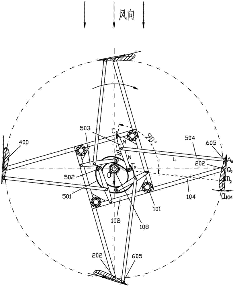
[0045] When the wind wheel rotates, the yaw wheel 502 runs in the grooved guide rail, which will produce a reaction force on the yaw guide wheel 501, so that the "direction diameter" cannot be consistent with the wind direction, resulting in yaw failure. Therefore, the yaw guide wheel 501 must be able to lock the wind direction at any time, and only rotate with the change of the wind direction, without being affected by other factors. The yaw system of the present invention is divided into two types according to different ways of adjusting and locking the wind direction: an active yaw system and a passive yaw system.
[0046] Image 6 A simplified schematic diagram of the structure of an active yaw system. The driving mechanism is a steering motor 510, and the steering motor 510 is connected to the vertical transmission shaft 515 through a steering worm 507. In the figure, the yaw wheel 501 is located in the grooved guide rail is the yaw wheel 502. The yaw wheel 502 is axially ...
Embodiment 2
[0048] See Figure 7 with Figure 8 , Is an example of the steering drive mechanism of a passive yaw system, which includes a steering gear 511 and a steering pinion 512. The steering gear 511 relies on a set of guide wheels 513 to be rotatably installed on the tower 300 in a horizontal state. A weather vane 514 is fixed on the steering gear 511; the steering pinion 512 is meshed with the steering gear 511, and the steering pinion 512 is connected to the worm of the steering worm gear 507 through a horizontal transmission shaft 515, and the worm gear is connected to the vertical The drive shaft 515 is connected.
[0049] The passive yaw system is used for non-power generation purposes (such as pumping water, etc.) in areas without electricity, and has unique advantages. The working principle of the system is similar to that of the active yaw system, and it also has a wind direction lock function. The difference is that the steering worm gear 507 is not driven by an electric moto...
Embodiment 3
[0052] Figure 9-11 It is another example of the passive yaw system, which is suitable for wind turbines using a truss-type tower with a larger span. Its working principle is the same as Figure 7-8 The same as shown, the steering drive mechanism includes a tubular shaft 516 rotatably mounted on the tower 300, a weather vane 514 is fixed on the tubular shaft 516, and a steering gear 511 is fixed on the tubular shaft 516. A steering pinion 512 is provided on the transmission shaft 515, and the steering large gear 511 meshes with the steering pinion 512. The steering pinion is connected to the worm of the worm gear 507, the lower end of the vertical transmission shaft 515 is connected to the worm gear, and the upper end is connected to the steering main gear 508.
[0053] The requirements for the components in the system are also similar, the difference is that the wind vane 514, the steering gear 511, the steering pinion 512 and other components are moved into the tower. The weat...
PUM
 Abstract
Description
Claims
Application Information