Eureka AIR delivers breakthrough ideas for toughest innovation challenges, trusted by R&D personnel around the world.

Numerical simulation of progressive lancing operation in sheet metal forming

A technology of cutting and sheet metal parts, applied in the field of computer-aided engineering analysis, can solve problems such as failure, numerical simulation numerical error, small finite element, etc.

Active Publication Date: 2015-02-11
LIVERMORE SOFTWARE TECH
View PDF3 Cites 3 Cited by
  • Summary
  • Abstract
  • Description
  • Claims
  • Application Information

AI Technical Summary

Problems solved by technology

Also, in addition to distorted FEA meshes, very small finite elements are created
As a result, numerical simulations can fail due to numerical errors in the handling of these elements, or become very long due to the size of these elements to maintain numerical stability

Method used


Image

  • Numerical simulation of progressive lancing operation in sheet metal forming
  • Numerical simulation of progressive lancing operation in sheet metal forming
  • Numerical simulation of progressive lancing operation in sheet metal forming

Examples


Embodiment Construction

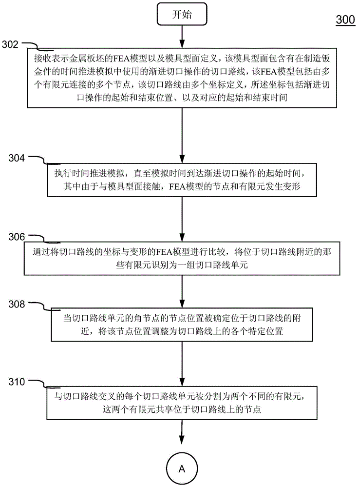
[0027] refer to Figure 3A and 3B , which collectively illustrate a flowchart of an exemplary method 300 for performing a time-marching simulation for the manufacture of a sheet metal part requiring progressive notching operations in accordance with an embodiment of the present invention. Method 300 is preferably implemented in software, and with reference to other figures (eg, Figure 4A-9 )understand.

[0028] Method 300 begins at step 302, in a computer system (e.g., Figure 10 computer system 1000) receiving a finite element analysis (FEA) model representing a sheet metal blank and a mold surface definition containing cut paths for a progressive cut operation used in a time-marching simulation of fabricating a sheet metal part . The FEA model includes multiple nodes connected by multiple finite elements (eg, 3 and / or 4 node shell elements). For example, Figure 4AThe illustrated FEA model 400 is a local mesh model representing a sheet metal blank prior to being machi...


PUM


Abstract

Systems and methods of conducting a time-marching simulation of manufacturing a sheet metal part that requires progressive lancing operation (PLO) are disclosed. The time-marching simulation is conducted with a connection-separation scheme for nodes along the lancing route to ensure a smooth timely separation of a lancing cut. The scheme includes creating a set of surrogate lancing route nodes by duplicating nodal coordinates of the existed nodes located along the lancing route. Nodal constraints to initially link together the existed nodes and the corresponding surrogate nodes are then created. The nodal constraint is removed in accordance with a separation time schedule established using start and end locations of the lancing route and corresponding start and end time for making the lancing cut. The nodal constraints can also be removed based on the zones of the lancing route defined by a user.

Description

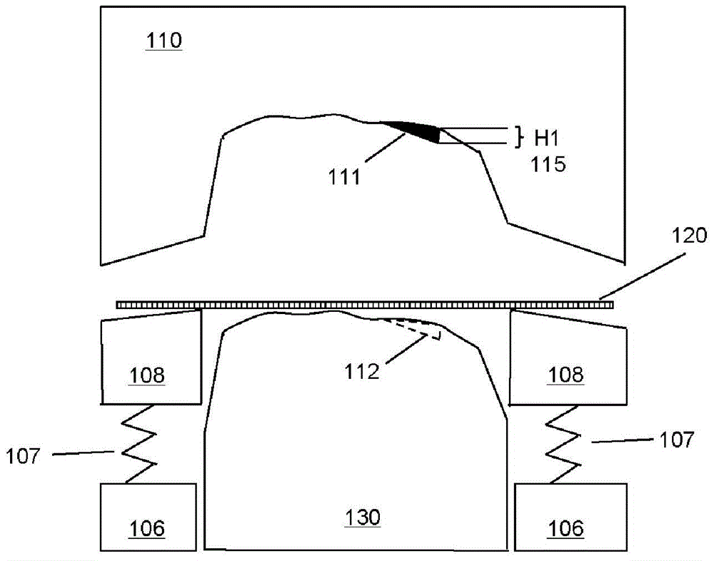
technical field [0001] The present invention relates generally to computer-aided engineering analysis for simulating sheet metal forming or stamping processes (e.g., deep drawing), and more particularly to methods and systems for performing time-marching simulations for manufacturing sheet metal parts that require Perform progressive lancing operation (PLO). Background technique [0002] Sheet metal forming has been used in industry for many years to form metal parts from sheet metal blanks, for example, automobile manufacturers and their suppliers use sheet metal forming to produce many parts. One of the most common sheet metal forming processes is known as stretch forming or stamping. figure 1 A cross-sectional view of an exemplary deep-draw stamping device is shown. To create a part or product, it uses hydraulic or mechanical pressure to advance a shaped die 110 onto a mating punch 130 with a sheet metal blank 120 or workpiece positioned between the die 110 and punch 13...

Claims


Application Information

Patent Timeline
IPC IPC(8): G06F17/50
CPCG06F17/5018G06F30/23G06F2113/22G06F2113/24
Inventor 朱新海张力
Owner LIVERMORE SOFTWARE TECH
Why Eureka
Eureka Blog
Learn More