Extracorporeal circulation cooling device for auxiliary electrolyzer

A technology of extracorporeal circulation and cooling device, applied in the direction of electrolysis process, electrolysis components, etc., can solve the problems of electrolyte corrosion to electric pump, waste of financial resources, etc., and achieve the effect of safe and reliable operation steps, energy saving, and simple operation steps.

Inactive Publication Date: 2016-09-28
邹小立
View PDF18 Cites 0 Cited by
  • Summary
  • Abstract
  • Description
  • Claims
  • Application Information

AI Technical Summary

Problems solved by technology

[0003] The purpose of the present invention is to provide an auxiliary electrolytic cell extracorporeal circulation cooling device to solve the problem that the electrolytic solution of the existing electrolytic cell seriously corrodes the electric pump during the external cooling process and requires frequent replacement of the electric pump, which consumes a lot of financial resources

Method used


Image

  • Extracorporeal circulation cooling device for auxiliary electrolyzer
  • Extracorporeal circulation cooling device for auxiliary electrolyzer
  • Extracorporeal circulation cooling device for auxiliary electrolyzer

Examples


specific Embodiment approach 1

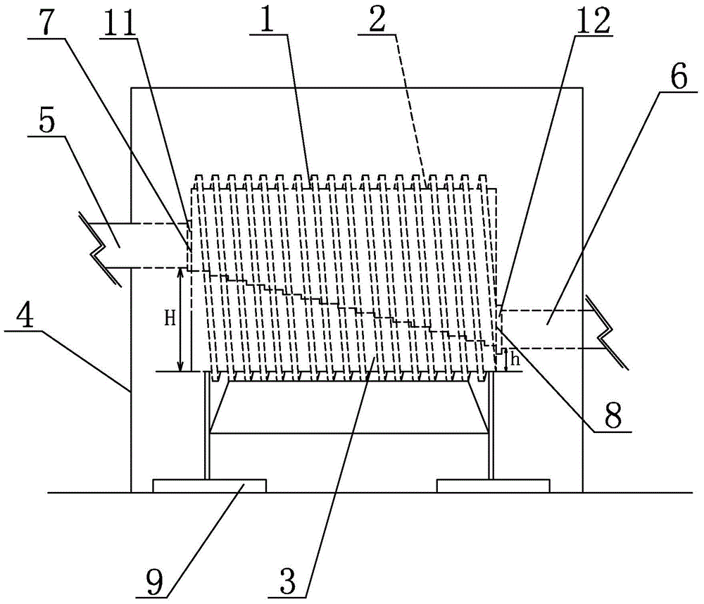
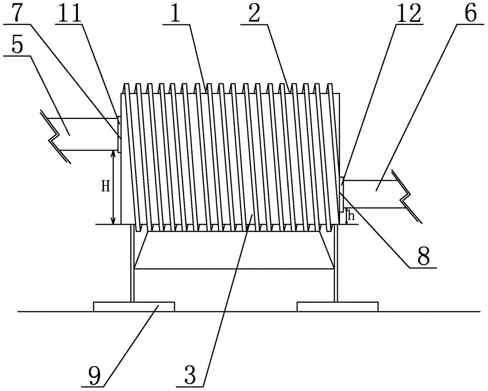
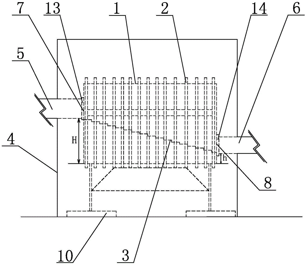
[0013] Specific implementation mode one: combine figure 1 , figure 2 , image 3 and Figure 4 Describe this embodiment, the auxiliary electrolytic cell extracorporeal circulation cooling device described in this embodiment includes a cooling main casing 1, a cooling pipe body 2, a stepped diverter plate 3, an outer cover body 4, a first pipeline 5 and a second Pipeline 6, the cooling main casing 1 is a sealed hollow body arranged horizontally, the cooling pipe body 2 is wound outside the cooling main casing 1 and arranged in a gap with the cooling main casing 1, the cooling main casing 1 An electrolyte inlet port 7 is processed on one side of the body, the first pipeline 5 communicates with the electrolyte inlet port 7, an electrolyte outlet port 8 is processed on the other side of the cooling main casing 1, and the second pipe The road 6 communicates with the electrolyte outlet port 8, the vertical distance from the electrolyte inlet port 7 to the bottom of the cooling ma...

specific Embodiment approach 2

[0015] Specific implementation mode two: combination figure 1 , figure 2 , image 3 and Figure 4 To describe this embodiment, the cooling main casing 1 in this embodiment is a cylinder or a cuboid. According to the specific working environment of the present invention, the cooling main housing 1 of suitable shape is selected to cool down the electrolyte in the electrolytic cell, and the volume of the cooling main housing 1 is 12000 cm 3 , when the cooling main casing 1 is a cylinder, the radius of the circular surface in the cylinder is 8.7cm, and the length is 50cm; when the cooling main casing 1 is a cuboid, the cuboid has a length of 50cm, a width of 30cm and The height is 8cm. Other components and connections are the same as those in the first embodiment.

specific Embodiment approach 3

[0016] Specific implementation mode three: combination figure 1 , figure 2 , image 3 and Figure 4 Describe this embodiment, in this embodiment, between the vertical distance H between the electrolyte inlet port 7 and the bottom of the cooling main casing 1 and the vertical distance h between the electrolyte outlet port 8 and the bottom of the cooling main casing 1 The distance difference is 8cm to 12cm. The optimal height difference between H and h is 10 cm, and this distance makes the cooling time and flow effect of the electrolyte in the cooling main casing 1 optimum. The other components and connections are the same as those in Embodiments 1 and 2.

[0017] Specific implementation mode four: combination figure 1 , figure 2 , image 3 and Figure 4 Describe this embodiment. In this embodiment, the cooling pipe body 2 is a spiral pipe body. On the cooling main casing 1. Other components and connections are the same as those in the third embodiment.


PUM

PropertyMeasurementUnit
radiusaaaaaaaaaa
lengthaaaaaaaaaa

Abstract

The invention discloses a device for assisting the cooling of extracorporeal circulation of an electrolytic bath and relates to a cooling device, aiming at solving the problems that an electric pump is seriously corroded by the electrolytic solution in the existing electrolytic bath during the extracorporeal cooling and is frequently changed to consume massive financial resources. A cooling tube body is wound outside a cooling main shell, and the cooling tube body and the cooling main shell are arranged in a clearance manner, an electrolytic solution inlet end is arranged on one side surface of the cooling main shell, a first pipeline is communicated with the electrolytic solution inlet end, an electrolytic solution outlet end is arranged on the other side surface of the cooling main shell, a second pipeline is communicated with the electrolytic solution outlet end, a vertical distance from the electrolytic solution outlet end to the bottom of the cooling main shell is less than a vertical distance H from the electrolytic solution inlet end to the bottom of the cooling main shell, ladder-shaped diversion plates are obliquely arranged in the cooling main shell, two ends of the ladder-shaped diversion plates are connected with an electrolytic solution inlet and an electrolytic solution outlet, and an outer cover covers outside the cooling main shell and the cooling tube body. The device is low in manufacturing cost and electricity-saving. The device is used for cooling the electrolytic bath.

Description

technical field [0001] The invention specifically relates to an extracorporeal circulation cooling device for an auxiliary electrolyzer. Background technique [0002] The hydrogen-oxygen gas machine is a new type of energy equipment. Its working principle is to electrolyze water to generate hydrogen-oxygen mixed gas, hydrogen combustion, oxygen combustion, and is used in many fields such as industrial cutting, welding and chemical industry. The core part of the hydrogen-oxygen gas machine is the electrolyzer, that is, the electrolyzed water part. The electrolyzer will generate temperature and heat during the process of electrolyzing water. As the temperature rises, water vapor will be generated, which will affect the quality of the hydrogen-oxygen mixed gas. In order to solve this problem, the cooling method commonly used in the current hydrogen-oxygen gas machine is to force the electrolyte to undergo extracorporeal circulation through an external power, that is, an electri...

Claims


Application Information

Patent Timeline
Patent Type & Authority Patents(China)
IPC IPC(8): C25B15/00C25B1/04
CPCY02E60/36
Inventor 邹小立
Owner 邹小立
Why Eureka
Try Eureka