High-compressibility and high-resilience sealing assembly

A sealing component, high-rebound technology, applied in the direction of engine sealing, engine components, mechanical equipment, etc., can solve the problems of seal leakage, loss of seal pressure, lack of seal pressure, etc., to ensure safe production, good rigidity, guarantee The effect of safe operation

Active Publication Date: 2015-02-18
SUZHOU BMC SEALING TECH CO LTD
View PDF10 Cites 5 Cited by
  • Summary
  • Abstract
  • Description
  • Claims
  • Application Information

AI Technical Summary

Problems solved by technology

In this case, the impact on the seal is very large. At high temperature, the seal will fail due to the expansion of the element and be crushed by overpressure. When the temperature drops, the shrinkage of the element will cause the seal to lose pressure, so that the sealing pressure Missing, causing seal leaks

Method used


Image

  • High-compressibility and high-resilience sealing assembly
  • High-compressibility and high-resilience sealing assembly
  • High-compressibility and high-resilience sealing assembly

Examples


Embodiment 1

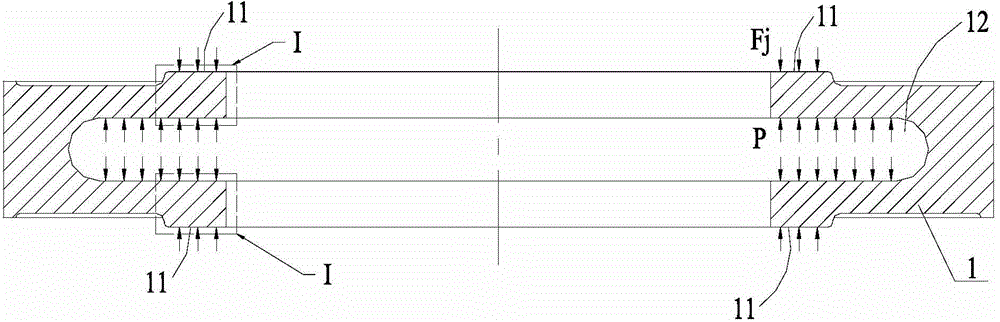
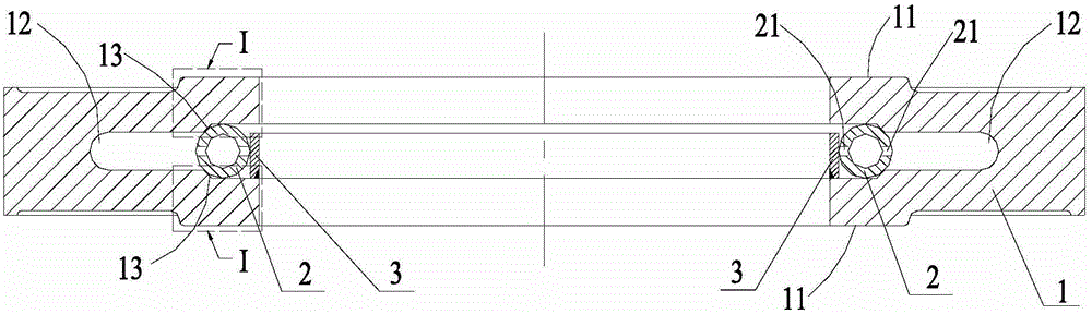
[0050] see Figures 1 to 5 A high compression and high resilience sealing assembly 100 is shown, the sealing assembly 100 includes a metal ring 1, the two axial end surfaces of the metal ring 1 are provided with a sealing structure 11 for sealing connection, and the sealing structure 11 is arranged on The radial direction of the metal ring 1 is used to bear the sealing stress or the side where the sealing stress is relatively large, and it is arranged on the inner side of the metal ring 1 , that is, the sealing structure 11 is arranged on two axial end surfaces of the radial inner side of the metal ring 1 .

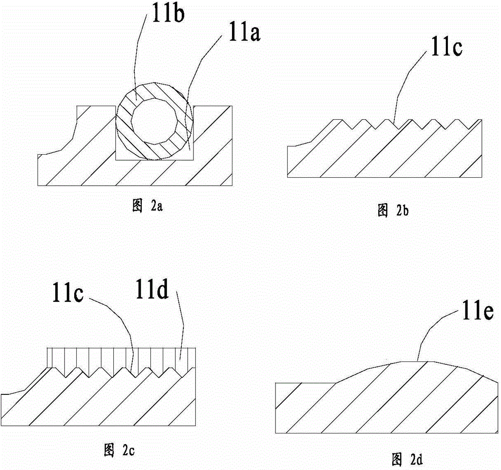
[0051] The sealing structure 11 can be as figure 2 The structural form of a, that is, an annular groove 11a is provided on the axial end surface of the metal ring 1, and an annular sealing ring 11b is arranged in the annular groove 11a, and the annular sealing ring 11b can play a role of metal wire sealing; is like figure 2 In the structural form of b, the axial ...

Embodiment 2

[0067] Such as Figures 9 to 11 As shown, the structure of the sealing assembly 100 in this embodiment is different from that in Embodiment 1 only in the arrangement of the annular groove and the arrangement position of the sealing structure. In this embodiment, an annular groove 16 is formed on the outer peripheral portion of the metal ring 1 , the opening of the annular groove 16 faces outward, and the sealing structure 17 is provided on two axial ends of the radially outer end of the metal ring 1 . The outer side of the annular groove 16 has an open end, and the bottom of the groove is a closed end. An elastic support is provided at the open end of the annular groove 16 .

[0068] This elastic support member can be elastic ring 6, as Figure 10 As shown, it is fixed in the annular groove 16 by the retaining ring 7. The arrangement of the elastic ring 6 and the retaining ring 7 is similar to the arrangement of the elastic ring 2 and the retaining ring 3 in Embodiment 1...

Embodiment 3

[0074] see Figure 13 As shown, the sealing assembly 100 is a collection of the sealing assemblies in Embodiment 1 and Embodiment 2, wherein the inner peripheral portion of the metal ring 1 is provided with an annular groove 12 with an opening facing inward, and the outer peripheral portion is provided with an annular groove 12 with an opening facing outward. Groove 16; on both sides of the metal ring 1, sealing structures are respectively provided at the radially inner and radially outer positions; elastic supports are respectively arranged in the annular groove 12 and the annular groove 16. This can have the effect of double sealing inside and outside.

[0075] The above sealing assembly 100 can also be set as Figure 14 In the structural form shown, the seal between the inner end and the outer end has good elasticity.

[0076] Such as Figure 15 As shown, the sealing assembly 100 is used for the sealed connection between the component 500 and the component 400. In ...


PUM


Abstract

The invention discloses a high-compressibility and high-resilience sealing assembly. The high-compressibility and high-resilience sealing assembly comprises a metal ring, wherein sealing structures for sealing connection are arranged on the two axial end surfaces of the metal ring, an annular groove with an opening is formed in the peripheral part of the inner side and / or the peripheral part of the outer side of the metal ring, the annular ring is provided with an open end and a closed end, an elastic supporting piece is fixedly arranged at the open end of the annular groove, the elastic supporting piece is supported between the upper side wall and the lower side wall of the open end along the axial direction of the metal ring in a retractable way, the open end is in liquid flow communication with the closed end through the elastic supporting piece, and the sealing structures are located on the two sides of the axial direction of the open end on the metal ring. The sealing assembly has the features of large compression amount and large resilience amount; when the sealing assembly is subjected to frequent compression and resilience during sealing connection, good rigidity can be kept, effective sealing load can be provided at the positions of the sealing structures, and the sealing connection positions are always guaranteed to be in an effective sealing state.

Description

[0001] technical field [0002] The invention relates to a high compression and high resilience sealing assembly. [0003] Background technique [0004] In the sealing system of nuclear power, thermal power, chemical industry, energy and other industrial sectors, there are often harsh working conditions such as high temperature, high pressure and alternating loads accompanied by thermal shock (thermal cycle) and medium pressure fluctuations. Heater, heat exchanger, reaction vessel, pipe seal. Under such working conditions of high temperature, high pressure and chemical reaction, due to the difference in thermal expansion of the various components of the equipment, the deformation of each component is inconsistent. In this case, the impact on the seal is very large. At high temperature, the seal will fail due to the expansion of the element and be crushed by overpressure. When the temperature drops, the shrinkage of the element will cause the seal to lose pressure, so that...

Claims


Application Information

Patent Timeline
Patent Type & Authority Applications(China)
IPC IPC(8): F16J15/06
CPCF16J15/06
Inventor 马志刚韩嘉兴朱建强马少骋
Owner SUZHOU BMC SEALING TECH CO LTD
Why Eureka
Try Eureka