Detection method for rectangular pin component visual positioning
What is AI technical title?
AI technical title is built by PatSnap AI team. It summarizes the technical point description of the patent document.
A pin component and visual positioning technology, which is applied in the detection field of visual positioning of rectangular pin components, can solve the problems of pin breakage and low positioning accuracy.
Inactive Publication Date: 2015-02-18
NANJING UNIV OF TECH
View PDF4 Cites 41 Cited by
Summary
Abstract
Description
Claims
Application Information
AI Technical Summary
This helps you quickly interpret patents by identifying the three key elements:
Problems solved by technology
Method used
Benefits of technology
Problems solved by technology
[0003] The present invention aims to solve the problem of low positioning accuracy of the traditional detection method for rectangular pin components, the pin is broken in the image, and separately detects the offset and deflection angle, and proposes a detection method for visual positioning of rectangular pin components
Method used
Image
Click on the blue label to locate the original text in one second.
Reading with bidirectional positioning of images and text.
Examples
specific Embodiment approach 1
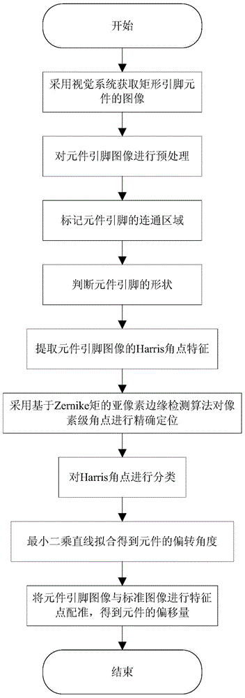
[0036] Specific Embodiment 1: A detection method for visual positioning of rectangular pin components described in this embodiment is implemented in the following steps:
[0037] Step 1: Use the placement machine vision system to obtain the image of the rectangular lead component.
[0038] Step 2: Preprocess the image obtained in Step 1, filter out the noise in the image, repair pin defects, and use the maximum inter-class variance method to perform threshold segmentation to obtain a binarized image.
[0039] Step 3: mark the connected region on the component pin image obtained in step 2.
[0040] The steps to mark the connected regions are:
[0041] Initialization: Randomly select a bright spot B in a connected area in the original image 0 .
[0042] Loop: use square structure element S to B 0 Perform expansion operation, the result after expansion intersects with the original image to get B 1 , repeat the expansion operation and intersection operation until B i+1 ==B ...
specific Embodiment approach 2
[0059] This embodiment is a further supplement to the specific embodiment one, and the Harris corner point extraction method described in step five is specifically implemented according to the following steps:
[0060] (1) Calculate the gradient I of the image I(x,y) in the x and y directions x , I y .
[0061] I x = ∂ I ∂ x = I ⊗ f x I y = ∂ I ∂ y = I...
specific Embodiment approach 3
[0074] Specific embodiment three: this embodiment is a further supplement to specific embodiment one, and the sub-pixel edge detection method based on Zernike moments described in step 6 is specifically implemented according to the following steps:
[0075] (1) According to the ideal model of sub-pixel edge detection, use the template of 7×7 to calculate the 5 rotated Zernike moments Z of each pixel-level corner point 00 ,Z 11 ,Z 20 ,Z 31 ,Z 40 .
[0076] (2) Calculate the 5 Zernike moments Z' after rotation 00 ,Z' 11 ,Z' 20 ,Z' 31 ,Z' 40 .
[0077] (3) Calculate the relationship between the edge parameters of the edge model and the rotated Zernike moments.
[0078] Z 00 ′ = ∫ - 1 l ∫ - 1 - x 2 ...
PUM
Abstract
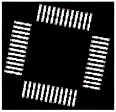
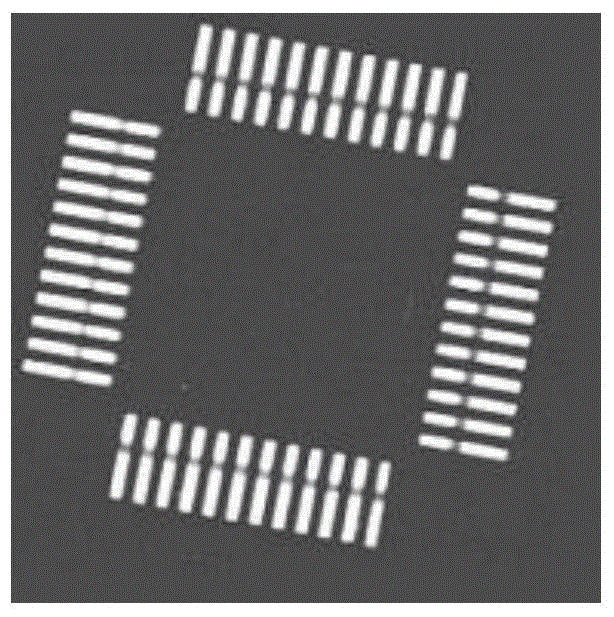
The invention provides a detection method for rectangular pin component visual positioning, and relates to the field of visual positioning and detection of rectangular pin components. The method aims to solve the problems that a traditional rectangular pin component detection method is low in positioning precision, pins break in images and deviation and deviation angles are detected separately. The method is characterized in that a measured component image is obtained by means of a chip mounter visual system, an image after binary pre-processing is obtained through threshold segmentation, a communication area of the component pins is marked, the shape of the component pins is judged, pixel-level Harris angular point coordinates of the pin image are extracted, sub-pixels of Harris angular points are solved and classified, the deviation angles of components are calculated, the pin image is matched with a standard image, and the deviation of the component is calculated. The method is mainly used for pin detection, deviation angle detection and deviation detection of the rectangular pin components.
Description
technical field [0001] The invention relates to the field of visual positioning and detection of rectangular lead components, in particular to a detection method for visual positioning of rectangular lead components. Background technique [0002] The visual positioning of rectangular lead components is to detect the offset of the component center relative to the nozzle center and the deflection angle of the component during the picking process, so that the servosystem can compensate the position of the component. Quickly and accurately completing the alignment of rectangular lead components plays a vital role in improving the work efficiency and precision of the placement machine. The existing detection of rectangular pin components is based on the inchworm creeping algorithm to detect the straight line features that make up the pins, and divides the edge pixel set into subsets with a certain gradient range according to the gradient direction, and then in each edge point su...
Claims
Application Information
Patent Timeline
Application Date:The date an application was filed.
Publication Date:The date a patent or application was officially published.
First Publication Date:The earliest publication date of a patent with the same application number.
Issue Date:Publication date of the patent grant document.
PCT Entry Date:The Entry date of PCT National Phase.
Estimated Expiry Date:The statutory expiry date of a patent right according to the Patent Law, and it is the longest term of protection that the patent right can achieve without the termination of the patent right due to other reasons(Term extension factor has been taken into account ).
Invalid Date:Actual expiry date is based on effective date or publication date of legal transaction data of invalid patent.

