High-temperature biaxial tension device
A biaxial stretching and high temperature technology, applied in the field of high-strength steel hot forming experiments, can solve the problems of inability to achieve bidirectional variable proportional loading, inconsistent stretching speed, and high price, and achieve simple structure, high precision and economical price. Effect
- Summary
- Abstract
- Description
- Claims
- Application Information
AI Technical Summary
Problems solved by technology
Method used
Image

Examples
Embodiment 1
[0096] Example 1: In the process of realizing bidirectional stretching, the ratio of speed in the horizontal and vertical directions is 1:1 and the stretching speed remains unchanged.
[0097] The working process includes the following steps:
[0098] 1. Use a cutting machine to cut a 350mm×90mm cross-shaped test piece blank with a material of 22MnB5, and process it into a test piece 28;
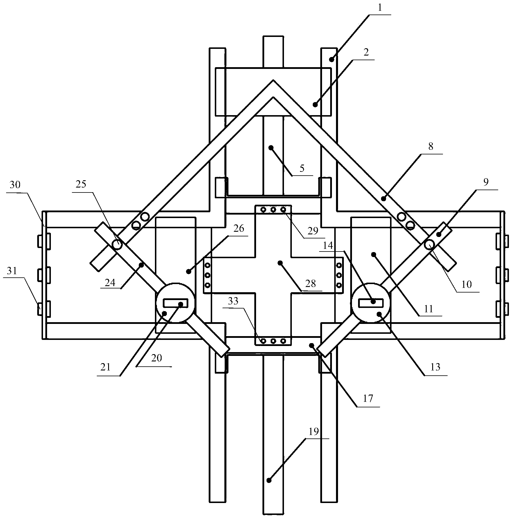
[0099] 2. Use a mechanical device to move the test piece 28 to the central position of the upper sliding block 6, the lower sliding block 17, the left sliding block 26 and the right sliding block 11, and use the test piece fixing bolt 29 and the test piece fixing plate 33 to place the test piece The upper fixed side, the lower fixed side, the left fixed side and the right fixed side of 28 carry out bolt connection with upper sliding block 6, lower sliding block 17, left sliding block 26, right sliding block 11 successively, thereby clamping test piece 28.
[0100] 3. Turn the right gear con...
Embodiment 2
[0104] Example 2: In the process of realizing bidirectional stretching, the ratio of speed in the horizontal and vertical directions is 1:2 and the stretching speed remains unchanged.
[0105] 1. Use a cutting machine to cut a 350mm×90mm cross-shaped test piece blank with a material of 22MnB5, and process it into a test piece 28;
[0106] 2. Use a mechanical device to move the test piece 28 to the central position of the upper sliding block 6, the lower sliding block 17, the left sliding block 26, and the right sliding block 11, and use the test piece fixing bolt 29 and the test piece fixing plate 33 to place the test piece The upper fixed side, the lower fixed side, the left fixed side and the right fixed side of 28 carry out bolt connection with upper sliding block 6, lower sliding block 17, left sliding block 26, right sliding block 11 successively, thereby clamping test piece 28.
[0107] 3. Turn the right gear control handle 14 so that the right No. 2 open slot of the rig...
Embodiment 3
[0111] Example 3: In the process of realizing bidirectional stretching, the ratio of speed in the horizontal and vertical directions is 1:3 and the stretching speed remains unchanged.
[0112] 1. Use a cutting machine to cut a 350mm×90mm cross-shaped test piece blank with a material of 22MnB5, and process it into a test piece 28;
[0113] 2. Use a mechanical device to move the test piece 28 to the central position of the upper sliding block 6, the lower sliding block 17, the left sliding block 26 and the right sliding block 11, and use the test piece fixing bolt 29 and the test piece fixing plate 33 to place the test piece The upper fixed side, the lower fixed side, the left fixed side and the right fixed side of 28 carry out bolt connection with upper sliding block 6, lower sliding block 17, left sliding block 26 and right sliding block 11 successively, thereby clamping test piece 28.
[0114] 3. Turn the right gear control handle 14 so that the right No. 3 open slot of the r...
PUM
| Property | Measurement | Unit |
|---|---|---|
| length | aaaaa | aaaaa |
| width | aaaaa | aaaaa |
| thickness | aaaaa | aaaaa |
Abstract
Description
Claims
Application Information
 - R&D
- Intellectual Property
- Life Sciences
- Materials
- Tech Scout
- Unparalleled Data Quality
- Higher Quality Content
- 60% Fewer Hallucinations
Browse by: Latest US Patents, China's latest patents, Technical Efficacy Thesaurus, Application Domain, Technology Topic, Popular Technical Reports.
© 2025 PatSnap. All rights reserved.Legal|Privacy policy|Modern Slavery Act Transparency Statement|Sitemap|About US| Contact US: help@patsnap.com