Retro-reflection measuring device

A measuring device and retro-reflection technology, which is applied in the field of optical radiation measurement, can solve the problems of incomplete optical signal of ring belt, difficulty in processing and fixing, and affecting measurement accuracy, etc.

Active Publication Date: 2015-02-18
HANGZHOU EVERFINE PHOTO E INFO
View PDF11 Cites 5 Cited by
  • Summary
  • Abstract
  • Description
  • Claims
  • Application Information

AI Technical Summary

Problems solved by technology

In this technical solution, multiple support devices are required to support the annular light-transmitting device. The introduction of multiple support devices will cause incomplete annular light signals and affect measurement accuracy; in addition, there is also a risk of instability in the fixation of the support devices. , thereby reducing the reliability and acc...

Method used


Image

  • Retro-reflection measuring device
  • Retro-reflection measuring device
  • Retro-reflection measuring device

Examples


Embodiment 1

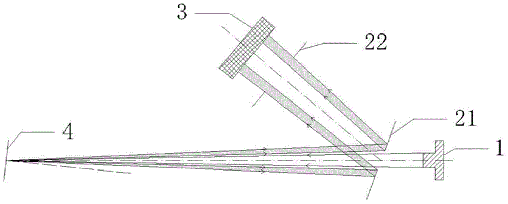
[0031] Such as figure 1 As shown, a retro-reflection measurement device for measuring a single observation angle is disclosed in this embodiment, comprising a light source 1, a sampling device 2, a measuring device 3 and a sample 4 to be measured, and the sampling device 2 consists of a perforated reflector 21 and a An optical path 22 is formed. The centers of the perforated reflector 21 and the aperture 22 are located on the optical axis. The light source 1, the perforated reflector 2, the sample to be measured 4, the aperture 22 and the measuring device 3 are sequentially arranged in the optical path.

[0032] This embodiment realizes the measurement of the retroreflection characteristics of the 0.2°±0.05° measurement ring corresponding to the 0.2° observation angle. The retro-reflected light is reflected to the apertured mirror 21, wherein the light with a beam angle greater than 0.15° reaches the aperture 22 along the observation optical path, and the light with a beam an...

Embodiment 2

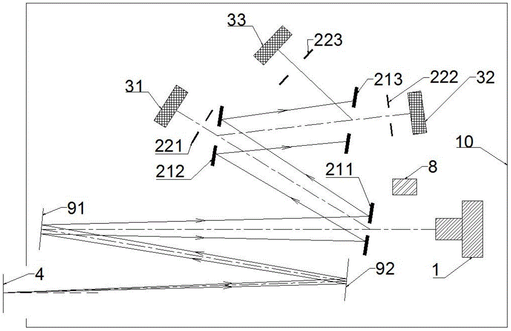
[0035] Such as figure 2 As shown, this embodiment includes a light source 1, a sampling device 2, a measuring device 3, a monitoring device 8, a reflector 9, and a chassis 10. The reflector 9 is arranged on the optical path between the light source 1 and the sample to be tested 4. The light source 1, The sampling device 2 , the testing device 3 , the monitoring device 8 , and the reflector 9 are all arranged in the case 10 . Different from Embodiment 1, the illumination light path in this embodiment does not directly reach the surface of the sample 4 to be tested, but reaches the surface of the sample 4 to be tested after two reflections by two mirrors 91 and 92, realizing the miniaturization of the instrument. Requirements; In addition, by setting three sets of sampling devices 2 (211 and 221, 212 and 222, 213 and 223), the measurement of annular light signals under three observation angles can be realized simultaneously.

[0036] The observation angles corresponding to the...

Embodiment 3

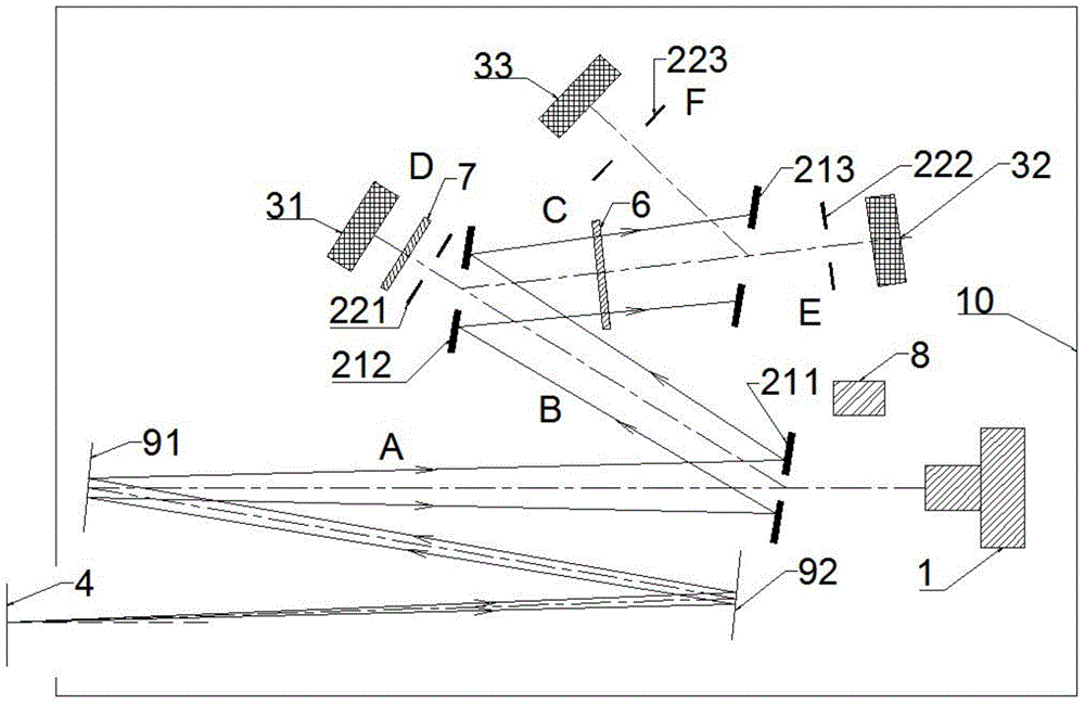
[0040] Such as image 3 As shown, different from Embodiment 2, this embodiment includes a color filter 6, and the color filter 6 is arranged behind the perforated reflector 212 of the second group of sampling devices, and the perforated reflector 213 of the third group of sampling devices The previous optical path is set in the common observation optical path C of the second group of sampling devices and the third group of sampling devices; both the measuring device 32 and the measuring device 33 are detectors, and the color filter 6 is CIE human eye spectral luminous efficiency Function V(λ), since the color filter 6 is arranged in the common observation optical path C, the light rays received by the measuring device 32 and the measuring device 33 are all light after the action of the color filter 6, that is, the measuring device 32 and the measuring device 33 Obtain photometric values ​​for different viewing angles.

[0041] This embodiment also includes a color filter disc ...


PUM


Abstract

The invention discloses a retro-reflection measuring device which adopts one or more sampling devices with diaphragms and reflectors with holes as well as one or more measuring devices corresponding to the sampling devices in quantity. Measurement of a plurality of retro-reflection characteristics under different observation angles can be achieved by one-time measurement, and the device can be suitable for accurate adjustment of various observation angles and the size of a measuring zone by flexibly selecting the sizes of the diaphragms and the reflectors with holes. No other intermediate device is needed and the optical signal of the zone is free of defects, so that the measuring accuracy is improved. Meanwhile, various color filters, a monitoring device and the like can be further flexibly arranged, so that the diversified measuring function is achieved. The device has the characteristics of fastness in measurement, high accuracy, small size, wide application range, powerful function, integral design and the like and can be widely applied to various occasions such as laboratories, industrial production lines, field fast measurement and the like.

Description

【Technical field】 [0001] The invention belongs to the field of optical radiation measurement, and in particular relates to a device for measuring retroreflection characteristics. 【Background technique】 [0002] Retro-reflective materials are mainly used in the field of traffic safety warning signs such as road traffic signs, markings, and various sight-guiding facilities. They play an important role in ensuring traffic safety. The measurement of retroreflection characteristics requires that the illumination angle and observation angle meet specific conditions. Since the angle is very small, it often requires a large measurement distance to accurately control the angle in actual measurement, and it needs to be carried out in a large dark room. It limits its application in actual engineering measurement, which also puts forward high requirements on the accuracy and reliability of instrument test results. In addition, in the industrial production line and on-site rapid measure...

Claims


Application Information

Patent Timeline
IPC IPC(8): G01N21/55
Inventor 潘建根
Owner HANGZHOU EVERFINE PHOTO E INFO
Why Eureka
Try Eureka