

Voltage sag detecting method suitable for dynamic voltage restorer
A technology of dynamic voltage recovery and voltage sag, applied in the measurement of current/voltage, instruments, measurement devices, etc., can solve the problems of inability to achieve dynamic tracking, large delay, poor anti-white noise ability, etc., to improve the fast response characteristics , Reduce the amplification effect, the effect of simple construction method
- Summary
- Abstract
- Description
- Claims
- Application Information
AI Technical Summary
Problems solved by technology
Method used
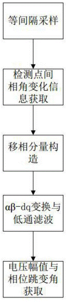
Image

Examples
Embodiment 1
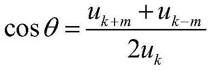
[0030] Select three sampling points at equal intervals as the front, middle and rear detection points u k-m , u k , u k+m , m can be the number of sampling intervals between adjacent detection points, the selection of parameter m is determined by the signal-to-noise ratio of the voltage signal to be observed and the voltage extraction accuracy requirements, and is inversely proportional to the signal-to-noise ratio of the observed voltage signal, T s is a fixed sampling interval, then the phase difference θ between adjacent detection points is:
[0031] cos θ = u k + m + u k - m 2 u k
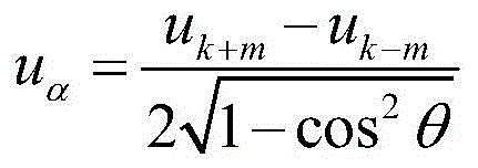
[0032] to u k u as α...
PUM
 Abstract
Description
Claims
Application Information