Image synthesis method, image chip and image equipment

An image synthesis and image chip technology, applied in the field of image processing, can solve the problems of reducing the efficiency of image synthesis, unable to maintain the time synchronization relationship, etc.

Active Publication Date: 2015-02-18
HUAWEI TECH CO LTD
View PDF5 Cites 24 Cited by
  • Summary
  • Abstract
  • Description
  • Claims
  • Application Information

AI Technical Summary

Problems solved by technology

[0004] In the prior art, the synthesis of images of multiple layers is completed in an offline mode, wherein the offline mode is to pre-read the layers to be displayed before displaying, and calculate the pixel value of each point in the terminal screen , and write it into a piece of memory, when it needs to be displayed, read the specific content from the written piece of memory and display it on the terminal screen, so the calculation of pixel values ​​can only be done after all layers are read in This makes it impossible to maintain a time synchronization relationship between the moment of calculating the pixel value and the moment of display. When there are many image frames to be displayed, it takes a long time to wait for the layer to be completely read and it takes more time to Calculate the pixel value, so the efficiency of image synthesis is reduced, which cannot meet the needs of current applications

Method used


Image

  • Image synthesis method, image chip and image equipment
  • Image synthesis method, image chip and image equipment
  • Image synthesis method, image chip and image equipment

Examples


Embodiment 1

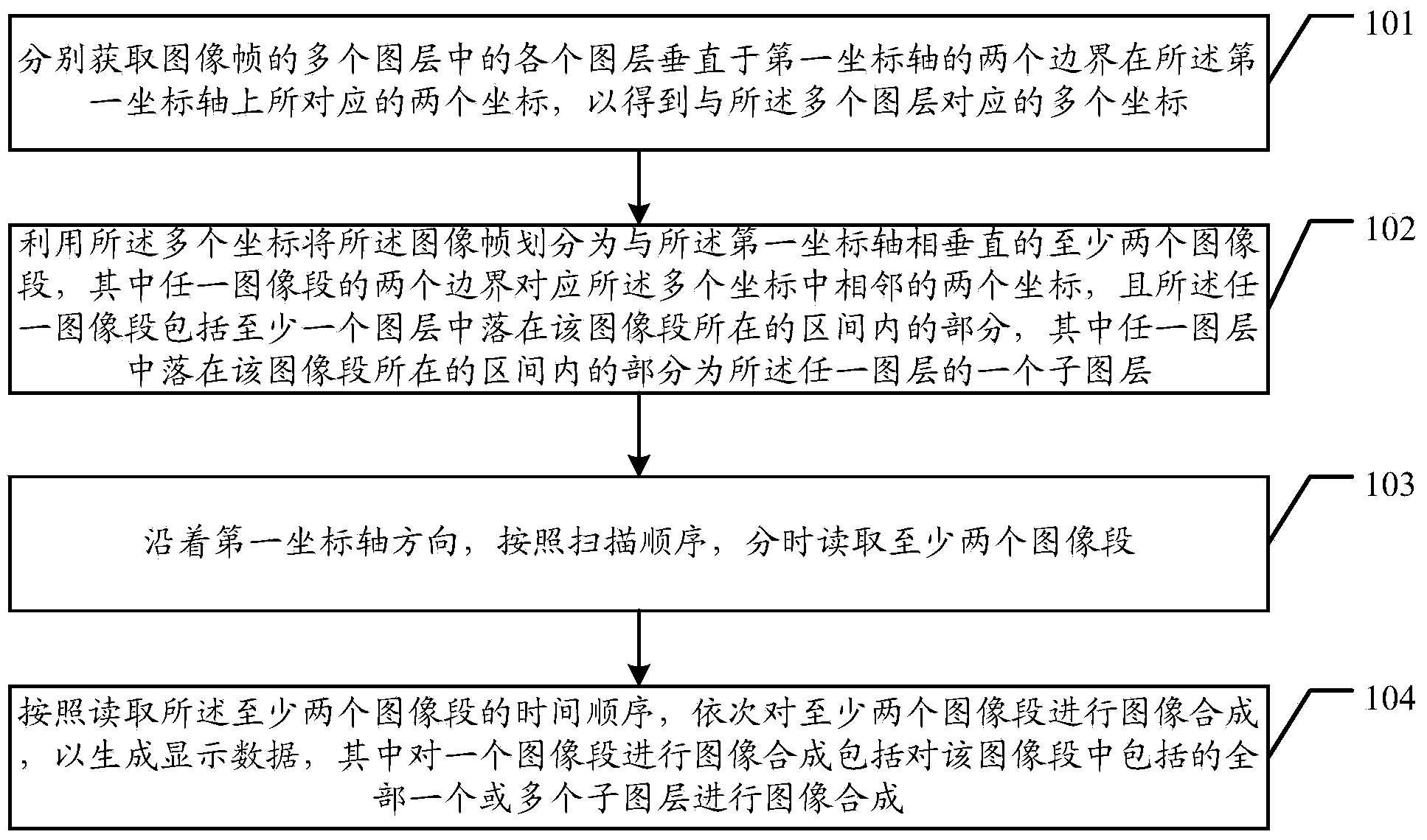
[0036] Such as figure 1 As shown, the embodiment of the present invention provides an image synthesis method, which can be applied to scenarios such as image synthesis processing, and the image synthesis method may include the following steps:

[0037] 101. Acquire the two coordinates on the first coordinate axis corresponding to the two boundaries of each layer in the multiple layers of the image frame to be displayed perpendicular to the first coordinate axis, so as to obtain the Layers correspond to multiple coordinates.

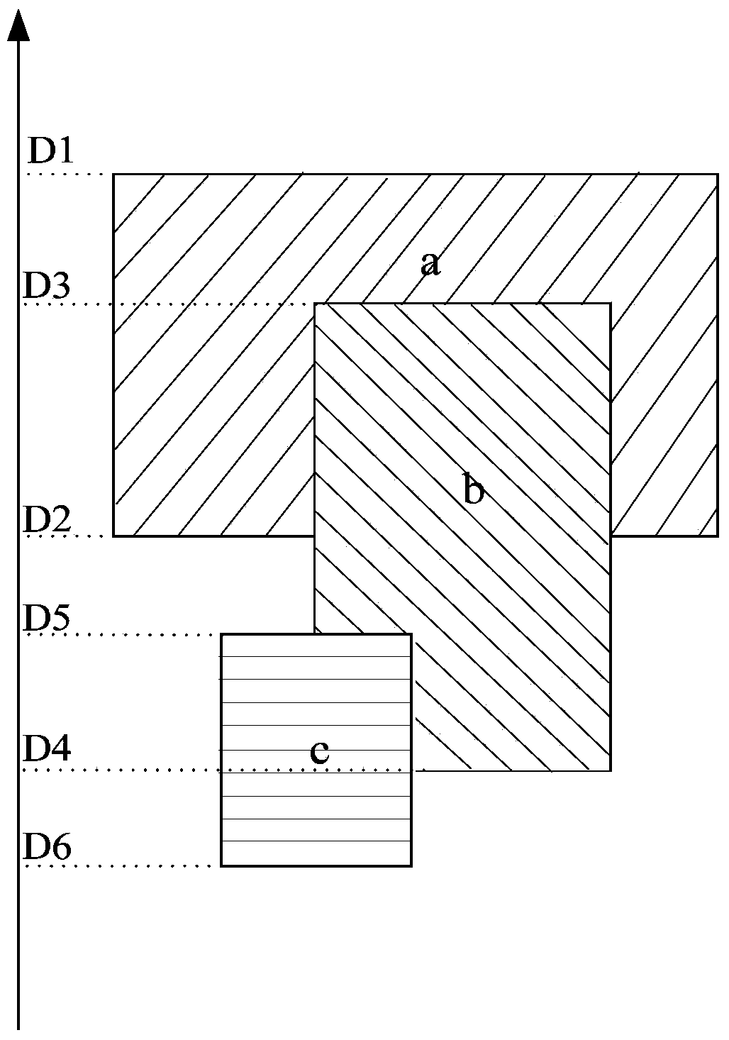
[0038] Those skilled in the art should know that when the image frame to be displayed is displayed on the terminal screen, since the image frame is usually composed of multiple layers, it is necessary to combine and display the various layers included in the image frame , in the embodiment of the present invention, when the coordinate system including the first coordinate axis is used as the reference system, each layer in the image frame to be displayed...

Embodiment 2

[0107] Such as Figure 5a As shown, an image chip 500 for image synthesis provided by an embodiment of the present invention may include: an acquisition unit 501, a layer division unit 502, an image reading unit 503, and an image synthesis unit 504, wherein,

[0108] The obtaining unit 501 is configured to respectively obtain two coordinates on the first coordinate axis corresponding to two boundaries of each layer in the multiple layers of the image frame to be displayed perpendicular to the first coordinate axis, so as to obtain a plurality of coordinates corresponding to the plurality of layers;

[0109] Those skilled in the art should know that an image chip usually includes a memory or cache for storing each layer of an image frame to be displayed, which is not shown in the figure for the sake of simplicity;

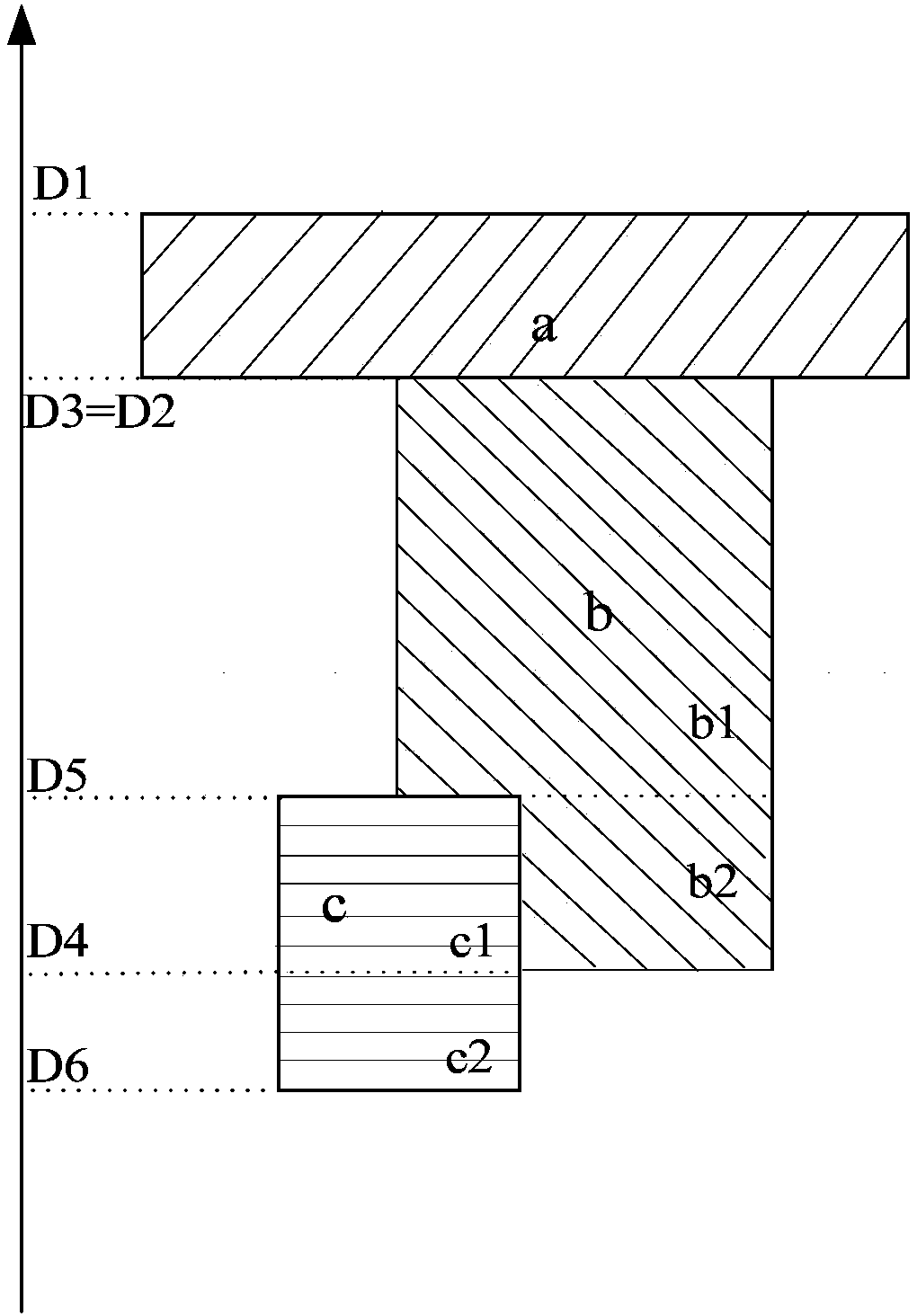
[0110] A layer division unit 502, configured to divide the image frame into at least two image segments perpendicular to the first coordinate axis by using the plu...

Embodiment 3

[0122] Such as Figure 6 As shown, the embodiment of the present invention also provides an image device 600, which may include: Figure 5a , 5b The image chip 500 and the display 601 described in any one of these, wherein,

[0123] The display 601 is configured to display display data generated by the image chip.

[0124] It should be known that the display 601 is usually used as a terminal screen in a mobile terminal or other home terminal, and its function is the same as that of the terminal screen described in the foregoing embodiments, and is used to display the display data generated by the image chip.

[0125] It can be understood that the image devices provided in the embodiments of the present invention may include but not limited to: mobile terminals, tablet computers, desktop computers, home terminals, and other product forms that require image synthesis.

[0126] From the above description of the embodiments of the present invention, it can be seen that since th...


PUM


Abstract

An embodiment of the invention discloses an image synthesis method, an image chip and image equipment. The image synthesis method comprises the following steps of respectively acquiring two coordinates, which correspond to two boundaries of each of a plurality of image layers of an image frame, on a first coordinate axis so as to obtain a plurality of coordinates corresponding to the image layers; dividing the image frame into at least two image segments which are perpendicular to the first coordinate axis by using the coordinates; reading the image segments at different times along the direction of the first coordinate axis according to a scanning sequence; and sequentially performing image synthesis of the image segments according to the time sequence on reading of the image segments so as to generate displaying data. The two boundaries of each of the image layers are perpendicular to the first coordinate axis.

Description

technical field [0001] The invention relates to the technical field of image processing, in particular to an image synthesis method, an image chip and an image device. Background technique [0002] The application usually displays content to the user in the form of a window on the terminal screen, that is, the image that the user sees through the terminal screen. When there are multiple applications that need to display content on the terminal screen, the image displayed on the terminal screen is often It is composed of multiple windows displayed by multiple applications. If the user opens an application, the application will present a window on the terminal screen and display the content on the window. At this time, if there is another application in the terminal An alert box pops up on the screen, and usually the alert box will cover part of the application window, so the final display on the terminal screen is the superimposed image of the window displayed by the applicat...

Claims


Application Information

Patent Timeline
Patent Type & Authority Applications(China)
IPC IPC(8): G06T3/40
CPCG06T5/50G06T2207/20212G06T3/40G06T11/40G06T7/11G06T7/13G06F3/0481G06T1/0007G06T11/60G06T2207/10016G06T2207/20021
Inventor 龚瑜龚芮陈静炜王永宏
Owner HUAWEI TECH CO LTD
Why Eureka
Try Eureka