
Plug-type button switch

A plug-in and push-button technology, which is applied in the field of plug-in push-button switches, can solve the problems of plug-in inductive switches that cannot meet the needs of use, small electrical load bearing capacity, and large wear of contact parts, so as to improve the operating characteristics and improve The effect of withstanding electrical load and improving electrical life

Active Publication Date: 2015-02-18
GUIZHOU ZHENHUA HUALIAN ELECTRONICS
View PDF7 Cites 0 Cited by
  • Summary
  • Abstract
  • Description
  • Claims
  • Application Information

AI Technical Summary

Problems solved by technology

The feature of the button switch is that it is installed in the machine and instrument in progress. Most of the time it is in the initial free state. It is only switched to the second state under the action of external force when required. Once the external force is removed, Due to the action of the spring, the switch returns to the initial position, its electrical load bearing capacity is small, the wear between the contacts is large, and the electrical life of the switch is short
Chinese patent ZL201220123401.2 discloses a plug-in sensor switch, the switch, the plug-in sensor switch is convenient for disassembly and line installation, realizes free plug-in, fast and effective connection of the circuit, and improves the efficiency of installation and use. Labor cost, and the installation can be done in one step without the need for other installation parts and installation tools such as screws and some related fasteners, but the plug-in sensor switch cannot be used under high current conditions

Method used


Image

  • Plug-type button switch
  • Plug-type button switch

Examples


Embodiment Construction

[0020] The technical solution of the present invention is further described below, but the scope of protection is not limited to the description.

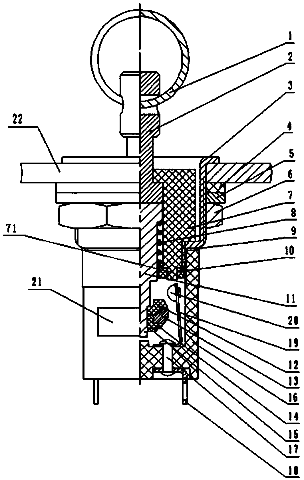
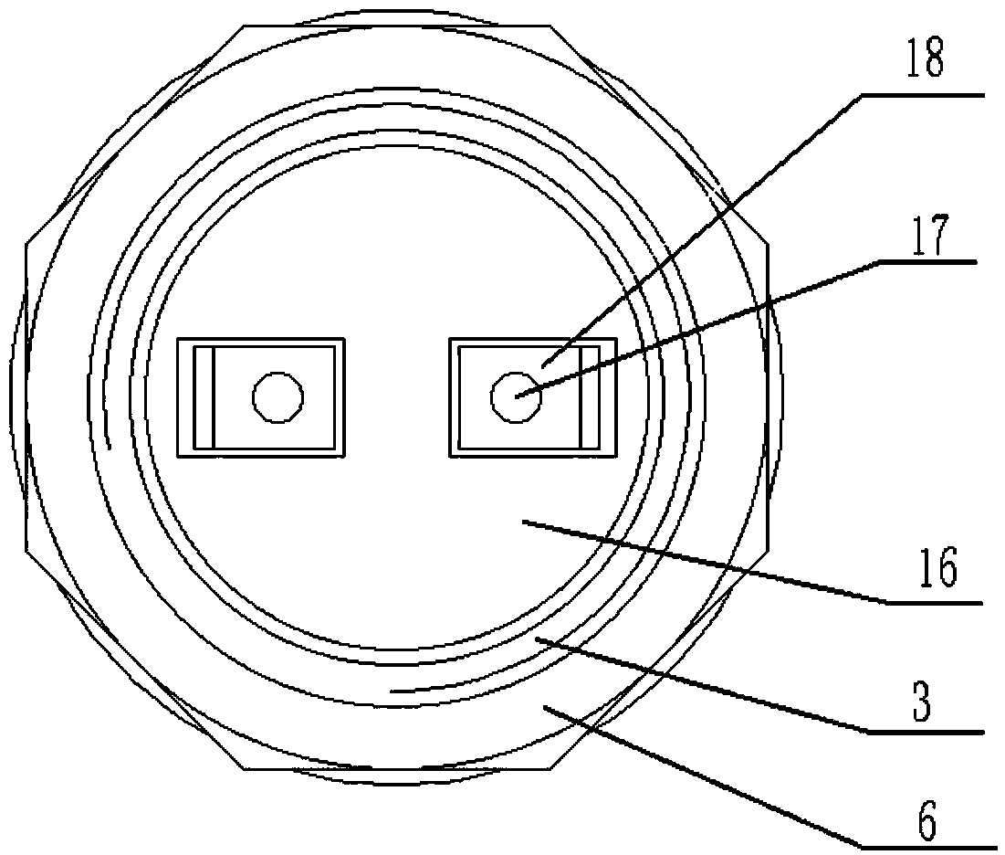
[0021] Such as figure 1 with figure 2 A plug-type button switch shown includes a handle 2, a housing 3, a washer 5, a nut 6, a base A7, a compression spring 8, a fixing plate 10, a push rod 11, a collar 15 and a mounting plate 22; The upper part of the base A7 is installed in the housing 3, and the lower part is fixedly connected with the base assembly through external threads; the housing 3 is fixedly installed on the mounting plate 22 through the washer 5 and the nut 6, and the top end of the push rod 11 is installed on the base assembly. In the seat A7, a compression spring 8 is arranged below the top step surface of the push rod 11, and the lower end of the compression spring 8 is installed on the upper side of the fixing plate 10, and the fixing plate 10 is fixed on the lower end surface of the base A7; The movable contact ...


PUM


Abstract

The invention provides a plug-type button switch which comprises a handle, a shell, a gasket, a nut, a base A, a pressure spring, a fixing plate, a push bar, a retainer ring and a mounting plate. The shell is fixedly mounted on the mounting plate through the gasket and the nut, the top end of the push bar is mounted in the base A, the pressure spring is arranged under the step surface of the top end of the push bar, the lower end of the pressure spring is fixedly mounted on the upper side of the fixing plate, and the fixing plate is fixed on a convex ring of the lower end surface of the base A. Switching on and off of a contact mechanism adopts a mode of touching of a contact point, so that the shortcoming that the on-off state is restored once external force is removed traditionally is overcome, abrasion among contact pieces is reduced, the contact point and a circular contact ring are made of silver oxide and indium tin oxide materials, electrical life of products under high current is prolonged, switching on-off locking of the switch can be realized, electrical load bearing capacity of the contact pieces is improved, usage period is prolonged, and accordingly, electrical life of the switch is prolonged.

Description

technical field [0001] The invention relates to the technical field of switch manufacturing, in particular to a plug-in push button switch. Background technique [0002] The push button switch is a switch that drives the internal contact conversion by the driving force on the same line as the push button stroke. The feature of the button switch is that it is installed in the machine and instrument in progress. Most of the time it is in the initial free state. It is only switched to the second state under the action of external force when required. Once the external force is removed, Due to the effect of the spring, the switch returns to the initial position, and its electrical load bearing capacity is small, the wear between the contacts is large, and the electrical life of the switch is short. Chinese patent ZL201220123401.2 discloses a plug-in sensor switch, the switch, the plug-in sensor switch is convenient for disassembly and line installation, realizes free plug-in, f...

Claims


Application Information

Patent Timeline
IPC IPC(8): H01H13/10H01H13/12H01H13/26
CPCH01H13/10H01H13/12H01H13/26H01H2201/028
Inventor 甘元发焦秋红朱姣
Owner GUIZHOU ZHENHUA HUALIAN ELECTRONICS
Learn More