Flow battery energy storage system for wave power generation

A liquid flow battery and energy storage system technology, which is applied in the direction of fuel cells, fuel cell additives, electrolyte flow processing, etc., can solve the problems of point-to-point power supply, too long cables, large line losses, and low power transmission efficiency. The effect of flexible power and capacity configuration, long service life and low transportation cost

Inactive Publication Date: 2015-02-18
DALIAN RONGKE POWER
View PDF2 Cites 7 Cited by
  • Summary
  • Abstract
  • Description
  • Claims
  • Application Information

AI Technical Summary

Problems solved by technology

However, due to the constraints of technology and cost, wave energy power generation technology has not been applied and developed on a large scale. The wave energy power generation in the prior art uses the mechanical energy generated by wave motion to drive the generator to generate electricity, and then transmits the electric energy to the The shore is connected to the power grid to achieve power supply. The existing problems are: the use of submarine cables for power transmission is expensive, the cable is too long, the line loss is large, the transmission efficiency is low, and there is a risk of scratching and damage to the submarine rock cable. , the wave power station in the prior art can only be built near the coast, which restricts and restricts the operation of the wave power station from offshore to the inland sea where wave energy is more abundant, and the power generation capacity is not strong. At the same time, long-term use of submarine cables will cause Problems such as aging and damage, and cables can only be powered point-to-point, resulting in a relatively single load, which cannot meet the power supply needs of multiple islands or loads for a set of wave energy power generation equipment

Method used


Image

  • Flow battery energy storage system for wave power generation

Examples


Embodiment Construction

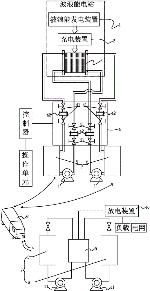
[0025] Such as figure 1 The shown flow battery energy storage system applied to wave energy power generation includes: a charging device 2 connected to a wave energy generating device 1, a stack group 3 connected to the charging device 2, and a pipeline system connected to all The electrolyte storage tank device 7 of the electric stack group 3; the electrolyte storage tank device 7 includes the positive electrode electrolyte storage tank 5 and the negative electrode electrolyte storage tank 6; the electric stack group 3, the pipeline system and the electrolyte storage tank The tank device 7 constitutes a flow battery system; the charging device 2 uses the electric energy output by the wave energy generating device 1 to charge the flow battery system; the electrolyte storage tank device 7 is separated from the stack group 3 Afterwards, it can be loaded and transported away by the transportation equipment 8; further, the electrolytic solution storage tank device 7 that is transp...


PUM


Abstract

The invention discloses a flow battery energy storage system for wave power generation. The flow battery energy storage system comprises a charge device which is connected with a wave power generation device, a galvanic pile group which is connected with the charge device, and an electrolyte storage device which is connected with the galvanic pile group through a pipeline system, wherein the electrolyte storage device comprises a positive electrode electrolyte storage tank and a negative electrode electrolyte storage tank; a flow battery system is formed by the galvanic pile group, the pipeline system and the electrolyte storage tank; the charge device is used for charging the flow battery system by virtue of the electric energy output from the wave power generation device; after being separated from the galvanic pile group, the electrolyte storage tank can be loaded and transported away through transportation equipment. The flow battery energy storage system is used for achieving on-site storage, effective transfer and targeted release of electric power converted from wave power, and is relatively flexible and reliable when being compared with a power transmission mode by virtue of seabed cables.

Description

technical field [0001] The invention belongs to the technical field of liquid flow batteries, in particular to a liquid flow battery energy storage system applied to wave energy power generation. Background technique [0002] Wave energy has the advantages of high energy density, wide distribution of resources, and environmental friendliness. It is an inexhaustible renewable clean energy. , The application potential is huge, so the utilization of wave energy has been highly valued by all ocean countries in the world. However, due to the constraints of technology and cost, wave energy power generation technology has not been applied and developed on a large scale. The wave energy power generation in the prior art uses the mechanical energy generated by wave motion to drive the generator to generate electricity, and then transmits the electric energy to the The shore is connected to the power grid to achieve power supply. The existing problems are: the use of submarine cables...

Claims


Application Information

Patent Timeline
Patent Type & Authority Applications(China)
IPC IPC(8): H01M8/04H01M8/24H01M8/04298H01M8/18H01M8/2465H01M8/2484
CPCH01M8/04283H01M8/249Y02E60/50
Inventor 张宇张华民苏小明杨振坤李颖王晓丽
Owner DALIAN RONGKE POWER
Why Eureka
Try Eureka