Method of producing a metal reinforcement for a turbine engine blade

A technology of metal reinforcements, reinforcements, applied in the direction of supporting elements of blades, components of pumping devices for elastic fluids, metal processing, etc.

Active Publication Date: 2015-02-18
SN DETUDE & DE CONSTR DE MOTEURS DAVIATION S N E C M A
View PDF7 Cites 17 Cited by
  • Summary
  • Abstract
  • Description
  • Claims
  • Application Information

AI Technical Summary

Problems solved by technology

Therefore, the position of the flaps a...

Method used


Image

  • Method of producing a metal reinforcement for a turbine engine blade
  • Method of producing a metal reinforcement for a turbine engine blade
  • Method of producing a metal reinforcement for a turbine engine blade

Examples


Embodiment Construction

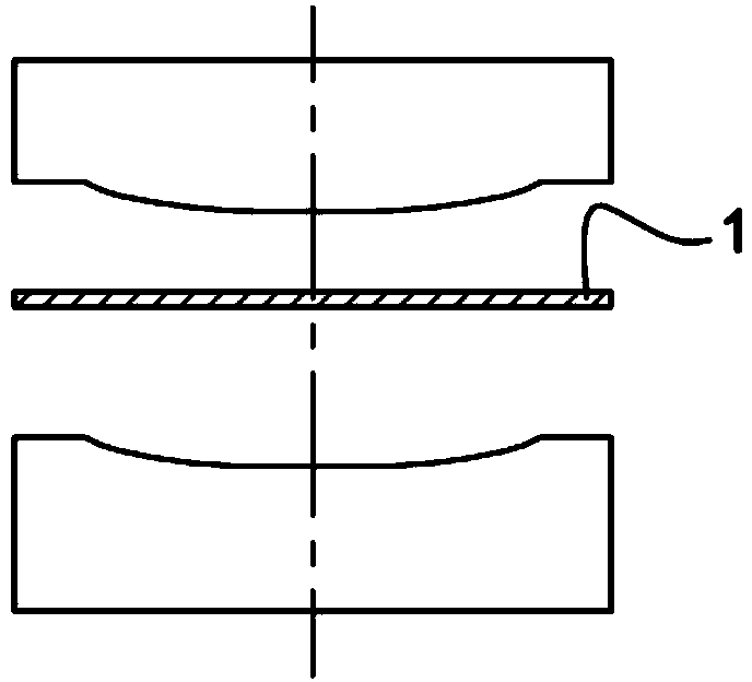
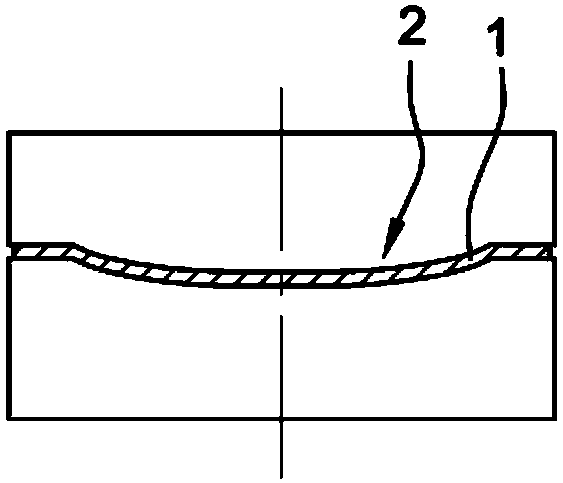
[0051] figure 1 The steps of hot pressing the metal sheets 1 are shown so as to bring their shape close to the final shape of the reinforcement to be manufactured. At the end of this forming operation, each metal sheet 1 has a concave area 2 defining a recess. The sheet 1 is made of a titanium-based alloy such as TA6V. This shaping step is carried out at a temperature of about 940°C.

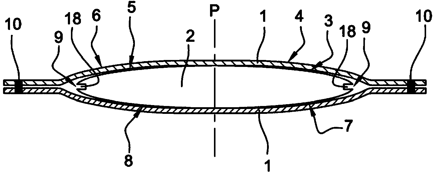
[0052] Such as image 3 As shown in , two identical metal sheets 1 are then placed face to face on either side of the core 2 , each concave side of the sheet 1 receiving a respective part of the core 2 .

[0053] The core 2 has a plane of symmetry P perpendicular to the sheet, comprising a first face that replicates for one half 3 the shape of the inner side of the pressure side of the first stiffener 4 to be produced, and for the other half The portion 5 replicates the inner shape of the suction side of the second stiffener 6 to be manufactured. The core 2 also comprises a second face oppo...


PUM


Abstract

The invention concerns a method of producing a metal reinforcement (4, 6) intended to be mounted on the leading edge (23) or trailing edge of a composite blade of a turbine engine, consisting of shaping two metal sheets (1), positioning them on each side of a core (2) comprising at least one recess intended to form a cavity for a wedge (19) for positioning the reinforcement (4, 6), assembling them under vacuum, shaping them on the core (2) by hot isostatic pressing, and cutting them to separate the reinforcement (4, 6) and release the core (2).

Description

technical field [0001] The invention relates to a method of manufacturing a metal reinforcement for mounting on the leading or trailing edge of a composite blade of a turbine engine, such as a fan blade of an aircraft turboprop or turbojet. Background technique [0002] To reduce the weight and cost of turboengine fan blades, they are often made of composite materials. Fan blades need to be able to withstand high levels of stress and impact due to their rotational speed and because of their resistance to impacts from particles or foreign objects that may penetrate the air passages. For this purpose, the front and / or rear edges of the blade made of composite material are protected by metal reinforcements adhesively bonded to the airfoil of the blade. [0003] Document EP1574270-A1 in the applicant's name describes a method for manufacturing reinforcements by diffusion welding and by superplastic forming and diffusion bonding (SPF / DB), said method comprising the following ste...

Claims


Application Information

Patent Timeline
IPC IPC(8): B21J5/12B21K3/04B21K23/00B21D53/78B23P15/04B64C11/20F01D5/14F01D5/28F04D29/02F04D29/32
CPCF04D29/324B21J5/12B23K9/167F04D29/023B21K3/04B23K2201/001B21D53/78B23K20/24B21D26/033B21D26/053Y02T50/672B21D35/00B23P15/04B23K20/021B23K2203/14B21K23/00F01D5/282B21D35/003B23K20/233B23K2101/001B23K2103/14F05D2240/303F05D2300/174F05D2300/702Y02T50/60Y10T29/49337F01D5/14F05D2300/603
Inventor 吉尔伯特·莱孔特吉勒斯·克莱恩吉恩-米歇尔·弗朗切特多米尼克·麦格德克斯
Owner SN DETUDE & DE CONSTR DE MOTEURS DAVIATION S N E C M A
Why Eureka
Try Eureka