Rotary shaft type steel bar splitting machine

A steel separating machine and rotating shaft technology, used in metal rolling, manufacturing tools, metal processing equipment, etc., can solve the problem that the steel pushing step distance cannot be accurately controlled, the contact distance between the pushing steel machine and the hot billet is close, and it is not easy to achieve. Automatic control and other issues, to achieve the effect of simple structure, light overall weight and uniform force

Active Publication Date: 2015-02-25
北京中冶设备研究设计总院有限公司
View PDF11 Cites 3 Cited by
  • Summary
  • Abstract
  • Description
  • Claims
  • Application Information

AI Technical Summary

Problems solved by technology

[0002] In the existing technology, the metallurgical industry often encounters the need to separate a group of continuous casting slabs together one by one and transport them longitudinally in sequence. The existing equipment mainly adopts the steel pushing method of hydraulic steel pushers to push the steel slabs in groups The outermost steel billet is pushed into the conveying roller table or transported away by other conveying equipment, which mainly has the following disadvantages: the scope of use is limited, and it can only be applied to the situation of no drop or small drop; the contact distance between the pusher and the hot billet is short, Severe heat radiation, harsh working conditions, and high failure rate; the reciprocating steel pushing movement of the steel pusher has a long cycle, frequent actions, and low efficiency; the steel pushing step cannot be accurately controlled to realize the steel separation function; it is difficult to realize automatic control; hydraulic cylinder Supporting hydraulic auxiliary facilities are required, and hydraulic oil is easy to leak and cause environmental pollution

Method used


Image

  • Rotary shaft type steel bar splitting machine
  • Rotary shaft type steel bar splitting machine
  • Rotary shaft type steel bar splitting machine

Examples


Embodiment Construction

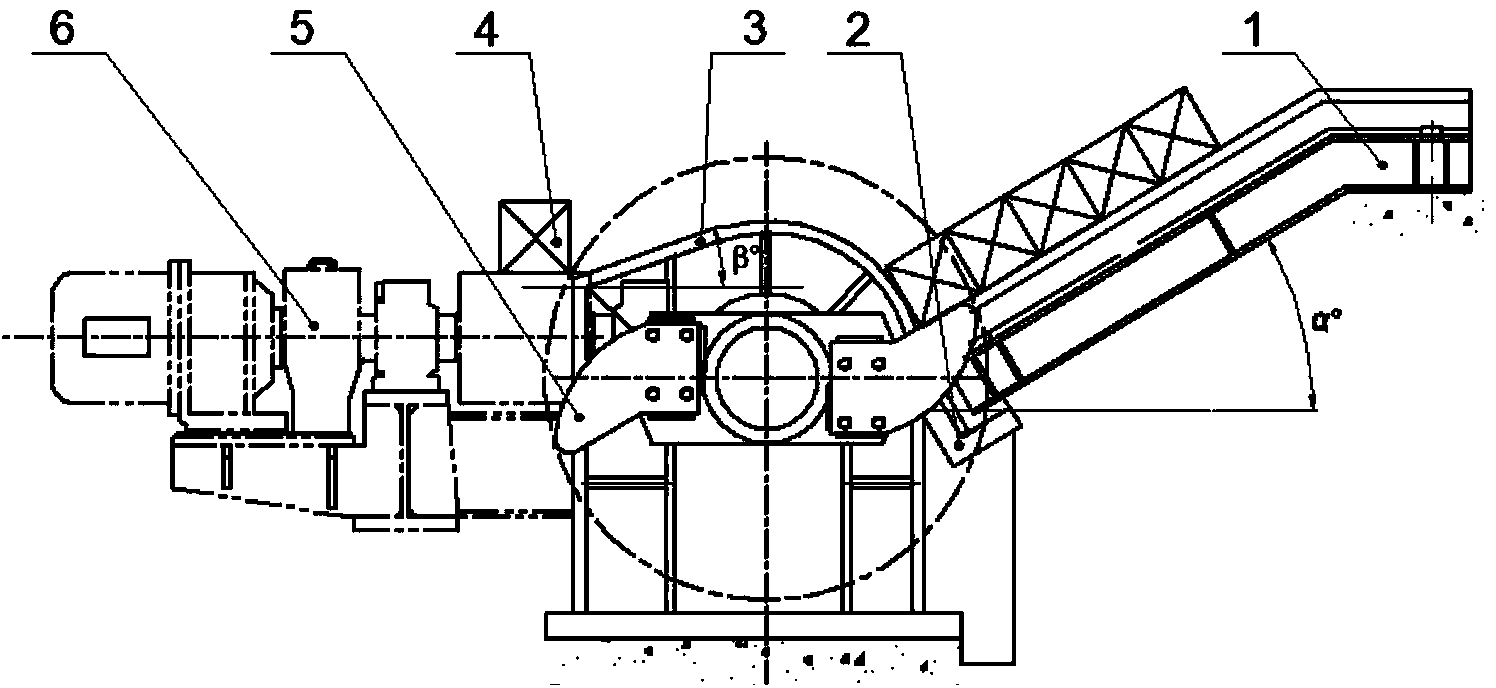
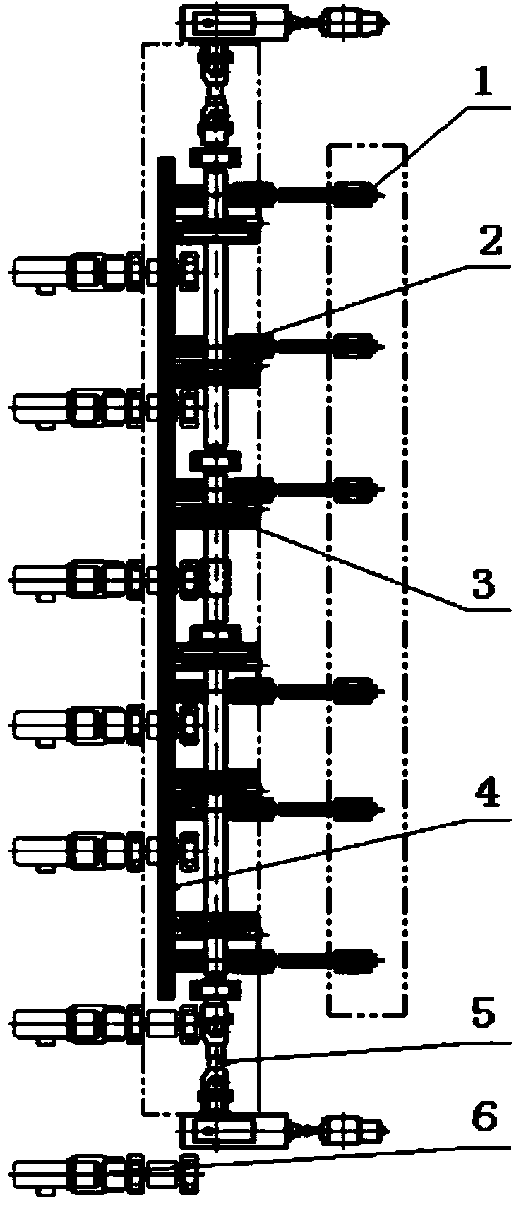
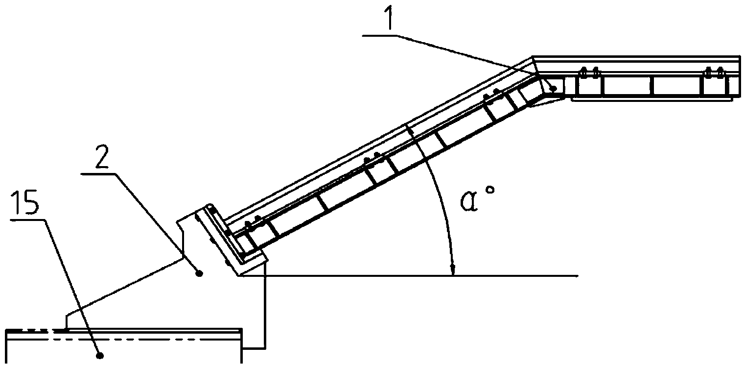
[0019] Embodiment of the present invention will be described in further detail below in conjunction with accompanying drawing: figure 1 , figure 2 A kind of rotating shaft type steel splitting machine shown, is made up of slide rail steel bench 1, steel bench seat 2, guide rail frame 3, steel splitter body 5; as image 3 Shown is a schematic diagram of the position connection of the steel frame 1, the frame seat 2, and the base 15. The steel frame 1 adopts a welded steel structure, and the standard light rail is fixed on the steel structure with bolts and pressure plates. Above, the steel platform base 2 is a welded steel structure, one end is fixed on the base 15 by bolts, and the other end is connected with the slide rail steel platform 1 through bolts, and the steel platform base 2 is designed with a detachable stopper , the welded steel structure base 15 is fixed on the foundation by anchor bolts, the inclination angle α of the slide rail connected to the steel platform ...


PUM


Abstract

The invention provides a rotary shaft type steel bar splitting machine. The rotary shaft type steel bar splitting machine comprises sliding rail steel connecting racks, a steel connecting rack seat, a steel bar splitting machine body and guide rail frames, and is characterized in that the sliding rail steel connecting racks, steel poking claws and the guide rail frames are sequentially arranged in the length direction of steel blanks in a staggered mode, the number of the sliding rail steel connecting racks, the number of the steel poking claws and the number of the guide rail frames are each at least two, and inclination angles of sliding rails of the sliding rail steel connecting racks enable steel blanks to automatically slide into steel through self gravity and be accurately positioned at the initial steel splitting position; the steel bar splitting machine body sequentially splits the steel blanks at the initial steel splitting position one by one, and the steel blanks move along guide rails of the guide rail frames and slide into conveying equipment connected with the guide rails; the steel bar splitting machine body adopts a double-side driving mode and is designed symmetrically; a key part long shaft of the steel bar splitting machine body is of a hollow shaft structure; the two steel poking claws are evenly distributed along the circumference; a water cooling sliding bearing seat is adopted, and a single-row roller chain coupler is adopted. The rotary shaft type steel bar splitting machine has the advantages of being simple in structure, convenient to maintain, light in weight, stable in operation, uniform in stress, long in service life, low in cost, capable of feeding steel automatically, accurate in positioning, saving in energy, environmentally friendly, and favorable for energy saving and consumption reduction of enterprises.

Description

Technical field: [0001] The invention relates to the technical field of continuous casting and steel rolling auxiliary equipment, in particular to a shaft-type steel splitter for separating a group of products (such as square billets, round billets, square steel, etc.) that are close together and have regular geometric shapes one by one for easy transportation . Background technique: [0002] In the existing technology, the metallurgical industry often encounters the need to separate a group of continuous casting slabs together one by one and transport them longitudinally in sequence. The existing equipment mainly adopts the steel pushing method of hydraulic steel pushers to push the steel slabs in groups The outermost steel billet is pushed into the conveying roller table or transported away by other conveying equipment, which mainly has the following disadvantages: the scope of use is limited, and it can only be applied to the situation of no drop or small drop; the contac...

Claims


Application Information

Patent Timeline
Patent Type & Authority Applications(China)
IPC IPC(8): B22D11/128B21B39/02
Inventor 侯青林曹燕平尚珂刘霄李金辉陈杰谭昕
Owner 北京中冶设备研究设计总院有限公司
Why Eureka
Try Eureka