Multifunctional automatic welding jig

An automatic welding and multi-functional technology, which is applied in the direction of welding equipment, auxiliary welding equipment, welding/cutting auxiliary equipment, etc., can solve the problems of increased manufacturing cost, large volume and weight, and a large number of tooling, so as to reduce production costs and general use Strong, the effect of improving the degree of flexibility

Active Publication Date: 2015-02-25
CRRC QINGDAO SIFANG CO LTD
View PDF11 Cites 8 Cited by
  • Summary
  • Abstract
  • Description
  • Claims
  • Application Information

AI Technical Summary

Problems solved by technology

Traditional beam clamps such as Figure 4 As shown, its length direction and width direction are fixed, it is only suitable for automatic welding of a single product, and its versatility is poor
[0006] Therefore, when automatically welding the side beams and beams of different models, it is necessary to switch between different fixtures. Due to the large volume and weight of the side beams and beams, the number of on-site tooling is large, the replacement is inconvenient, and the manufacturing cost increases. management difficulties

Method used


Image

  • Multifunctional automatic welding jig
  • Multifunctional automatic welding jig
  • Multifunctional automatic welding jig

Examples


Embodiment Construction

[0028] Attached below Figures 5 to 7 The present invention is described in further detail.

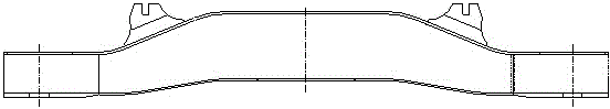
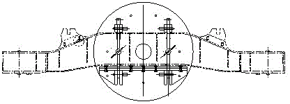
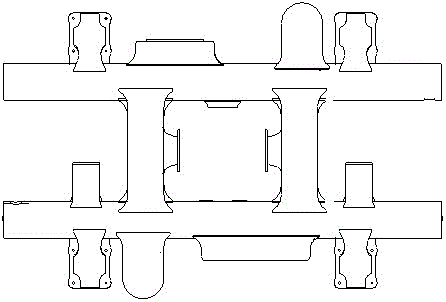
[0029] Such as Figure 5 As shown, the multifunctional automatic welding fixture of the present invention includes: a fixture main body 1, a transition plate 2, a side beam adjustment mechanism 3, a cross beam adjustment mechanism 4, a lateral beam pressing mechanism 5, and a side beam end positioning mechanism 8.

[0030] Such as Image 6 As shown, the fixture main body 1 is a welded structure of two rectangular steel pipes and steel plates, which has high rigidity and meets the requirement of rigid fixation.

[0031] The transition plate 2, the center of which is connected to the middle part of the bottom surface of the clamp body 1 through a pin shaft, serves as a connection between the clamp body of the present invention and the welding robot, and the pin shaft is used for positioning so that the center line of the clamp body coincides with the robot turntable clamp, thereby Gu...


PUM


Abstract

The invention discloses a multifunctional automatic welding jig. The multifunctional automatic welding jig comprises a jig body, a side beam adjustment mechanism, cross beam adjustment mechanisms, cross beam and side beam pressing mechanisms and a transition disc, wherein the jig body is formed by welding two pieces of square steel and a steel plate, the two pieces of square steel are parallel to each other, the side beam adjustment mechanism is fixed to the middle upper portion of the jig body and is composed of a bottom surface, a top surface, a plurality of tension bolts and a plurality of puller bolts, the bottom surface is parallel to the top surface, the tension bolts and the puller bolts are arranged between the bottom surface and the top surface, the cross beam adjustment mechanisms are fixed to the two sides of the jig body, the two sides of each cross beam adjustment mechanism are each provided with two transverse steel plates, a series of long through sliding grooves which are parallel to one another are formed in each steel plate, V-shaped blocks are matched with the sliding grooves through sliding blocks on the sliding grooves, the cross beam and side beam pressing mechanisms are arranged at the two ends of the jig body, and each cross beam and side beam pressing mechanism comprises a supporting plate fixed above the jig body, a bolt, a cross beam pressing plate and a side beam pressing plate. The multifunctional automatic welding jig has the advantages that the universality is high, the welding jig can meet the requirement for automatic welding of various side beams in two different kinds of structures and sizes and various cross beams in two different kinds of structures and sizes, tool manufacturing cost is reduced, a small storage site is occupied, and the flexibility of the automatic welding process is improved.

Description

technical field [0001] The invention relates to a fixture, in particular to a multifunctional automatic welding fixture suitable for side beams and beams of different specifications on rail vehicles. [0002] Background technique [0003] The traditional automatic welding fixture is a special fixture, which corresponds to the relevant automatic welding fixture according to the type and size of the product. [0004] Rail vehicle side beams such as figure 1 As shown in , its length and height vary depending on the model. Traditional side beam welding fixtures such as figure 2 As shown, the central positioning and compression structure is adopted, causing part of the weld seam of the side beam to be blocked by the fixture, and continuous welding of the full-length weld seam cannot be realized. Therefore, there are joints in the weld seam of the side beam, and the joints need to be manually polished after automatic welding. Supplementary welding leads to low degree of autom...

Claims


Application Information

Patent Timeline
Patent Type & Authority Applications(China)
IPC IPC(8): B23K37/04
CPCB23K37/0435B23K2101/28
Inventor 李文张志毅吴发杰陈北平张世欣李阳
Owner CRRC QINGDAO SIFANG CO LTD
Why Eureka
Try Eureka