Low-temperature differential thermal control device for infrared horizon sensors of orbit transfer vehicle

An infrared horizon and orbit transfer technology, which is applied in the direction of the device for controlling the living conditions of the spacecraft, can solve the problems of exceeding the target range, potential safety hazards, and approaching working temperature, so as to reduce low-temperature heat leakage, high reliability, and enhanced adaptive effect

Active Publication Date: 2015-02-25
SHANGHAI SATELLITE ENG INST
View PDF6 Cites 10 Cited by
  • Summary
  • Abstract
  • Description
  • Claims
  • Application Information

AI Technical Summary

Problems solved by technology

However, the two infrared horizons of the transfer orbiter are installed at the junction of the sunny side and the back side. Affected by the maneuvering orbit change, the horizon will be exposed to different degrees of direct sunlight, the external high temperature environment is harsh, and the two horizons are not exposed to the sun. Similarly, if the thermal design method of the general satellite infrared horizon is fully covered with multiple layers, and the design idea is unified, it will inevitably cause the working temperature of the infrared horizon to approach or even exceed the upper limit of the high temperature under high temperature conditions, or a certain one can meet the requirements. But the other one is close to or even exceeds the range of the index, which brings security risks

Method used


Image

  • Low-temperature differential thermal control device for infrared horizon sensors of orbit transfer vehicle
  • Low-temperature differential thermal control device for infrared horizon sensors of orbit transfer vehicle
  • Low-temperature differential thermal control device for infrared horizon sensors of orbit transfer vehicle

Examples


Embodiment Construction

[0026] The present invention will be described in detail below in conjunction with specific embodiments. The following examples will help those skilled in the art to further understand the present invention, but do not limit the present invention in any form. It should be pointed out that for those of ordinary skill in the art, a number of modifications and improvements can be made without departing from the concept of the present invention. These all belong to the protection scope of the present invention.

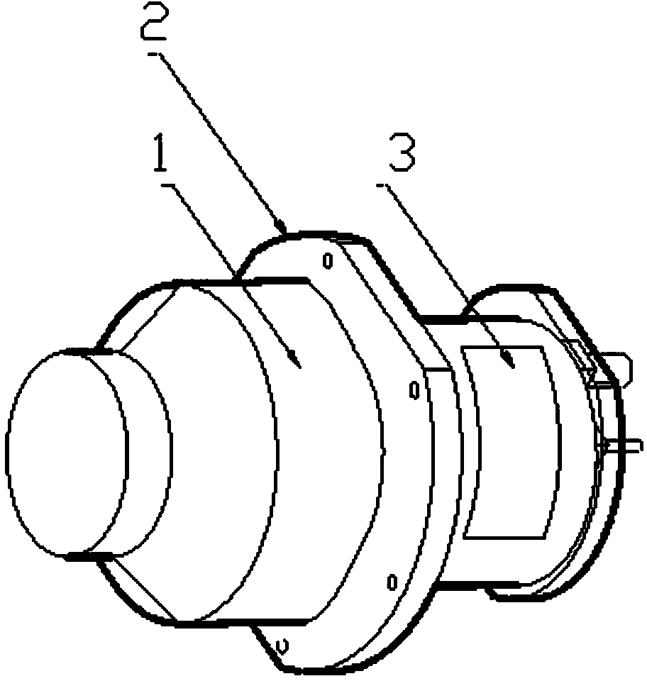
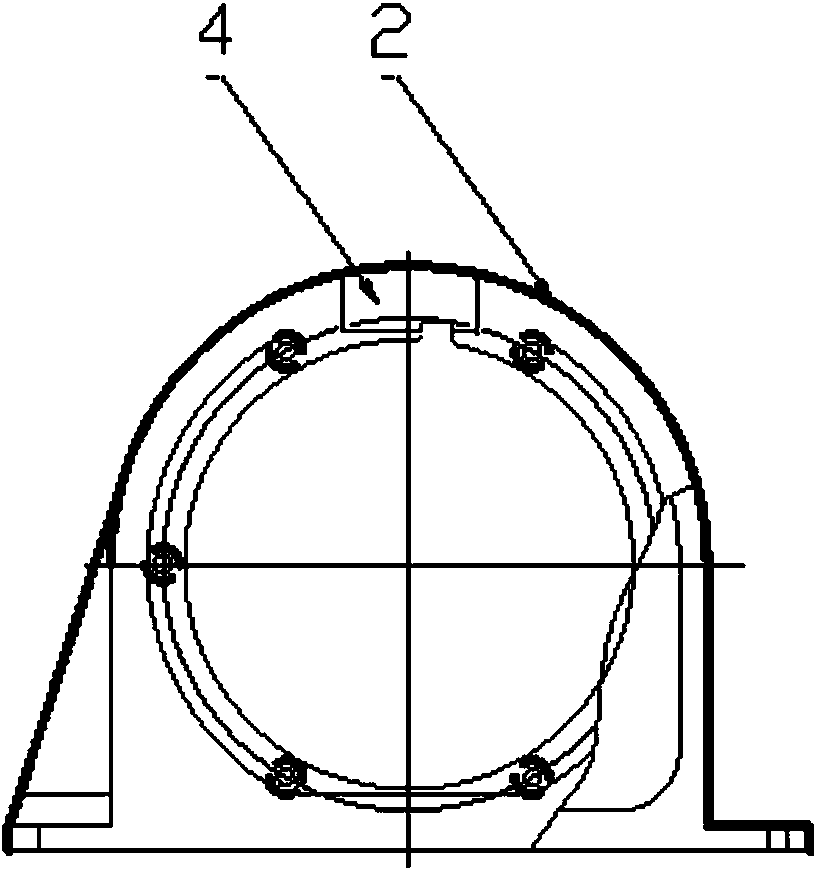
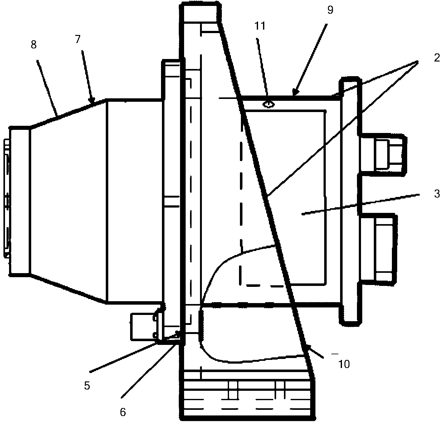
[0027] The invention provides a low-temperature differential thermal design technology for an infrared horizon meter of an orbit transfer aircraft, which includes heat insulation pad 1, S781 white paint thermal control coating 2, multilayer heat insulation component 3, thermistor 4, and electric heater 5.

[0028] First, paste the thermistor 4 and heater 5 on the heads of the tilting and rolling horizons respectively to ensure that the heater is well attached to the surface ...


PUM


Abstract

The invention provides a low-temperature differential thermal control device for infrared horizon sensors of an orbit transfer vehicle. The low-temperature differential thermal control device comprises a thermal insulation gasket, an S781 white paint thermal control coating, a multilayer thermal insulation assembly, an electric heater, a thermistor, the horizon sensors and horizon sensor supports. Independent heat dissipation faces are formed on the infrared horizon sensors for the first time, the positions of the heat dissipation faces formed on the pitching horizon sensor and the rolling horizon sensor are different according to different illumination conditions, implementation is convenient, reliability and adaptability are high, the total resource occupation amount is small, thermal resistance between a star and the infrared horizon sensors is increased through the thermal insulation gasket, a basis is provided for independent temperature control of the horizon sensors, the independent heat dissipation faces are formed on the heads of the infrared horizon sensors so as to achieve a low-temperature design thought, the S781 white paint thermal control coating is sprayed, differential thermal design of the infrared horizon sensors is achieved, and adaptability of horizon sensor maneuvering orbits is improved.

Description

Technical field [0001] The invention belongs to the field of spacecraft thermal control design, and particularly relates to a low temperature differential thermal design technology for an orbit transfer aircraft infrared horizon instrument. Background technique [0002] The test target orbit of a certain type of aircraft needs to be able to adapt to the change of the orbital altitude of 500-800km at 6:30±30min at the descending node. The aircraft requires multiple maneuvering changes in orbit. Large changes in orbital conditions cause large changes in the external heat flow conditions of the aircraft, and the exposure of the external single aircraft is complicated. Therefore, the thermal control design of the aircraft, especially the external single aircraft thermal environment, is required to have high adaptability. The aircraft uses two infrared horizon meters: rolling horizon and pitch horizon. The head of the horizon instrument is installed on the outer surface of the aircra...

Claims


Application Information

Patent Timeline
Patent Type & Authority Applications(China)
IPC IPC(8): B64G1/50
Inventor 耿宏飞王江曹建光王骢
Owner SHANGHAI SATELLITE ENG INST
Why Eureka
Try Eureka