Measurement device and method for fiber loop fusion point reflection in photonic bandgap fiber gyroscope

A photonic band gap and fiber optic gyroscope technology, which is applied to measurement devices, instruments, etc., can solve the problems of testing, limited spatial resolution, and inability to use melting point reflection, and achieve the effect of high precision and simple measurement method.

Active Publication Date: 2015-02-25
BEIHANG UNIV
View PDF7 Cites 15 Cited by
  • Summary
  • Abstract
  • Description
  • Claims
  • Application Information

AI Technical Summary

Problems solved by technology

Due to the limited spatial resolution of OTDR, this test method is not accurate enough. At the same time, when both ends of the fiber ring are fused with the Y waveguide pigtail, the optical path is closed, and the melting point reflection cannot be tested by OTDR.

Method used


Image

  • Measurement device and method for fiber loop fusion point reflection in photonic bandgap fiber gyroscope
  • Measurement device and method for fiber loop fusion point reflection in photonic bandgap fiber gyroscope
  • Measurement device and method for fiber loop fusion point reflection in photonic bandgap fiber gyroscope

Examples


Embodiment Construction

[0030] The present invention will be further described in detail with reference to the accompanying drawings and embodiments.

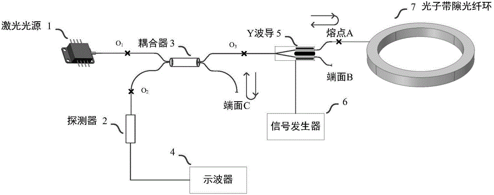
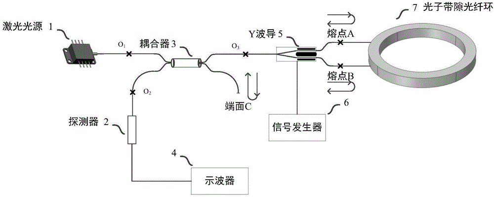
[0031] The invention is a measurement device for the reflection of the fusion point of the optical fiber ring in the photonic bandgap optical fiber gyroscope, such as figure 1 As shown, it includes a laser light source 1, a coupler 3, a Y waveguide 5, a photonic bandgap fiber ring 7, a detector 2, a signal generator 6, and an oscilloscope 4;

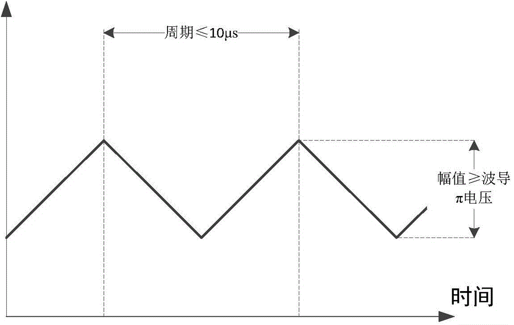
[0032] The output pigtail of laser source 1 and the O of coupler 3 1 The pigtails are connected by a flange, and the O of the coupler 3 2 end with detector 2 pigtail spliced, coupler O 3 End and Y waveguide 5 input pigtails are welded, and Y waveguide 5 output pigtails are provided with end face A and end face B. According to the measurement needs, choose end face A or end face B to be welded with photonic bandgap fiber ring 7 pigtails, and the melting points are A or B respectively. B. The signal generator 6...


PUM


Abstract

The invention discloses a measurement device and method for fiber loop fusion point reflection in a photonic bandgap fiber gyroscope. The measurement device comprises a laser source, a coupler, a Y-waveguide, a photonic bandgap fiber loop, a detector, a signal generator and an oscilloscope. An output tail fiber of the laser source is in butt joint with a tail fiber O1 of the coupler through a flange, an end O2 of the coupler is welded with a tail fiber of the detector in a fusion manner, an end O3 of the coupler is welded with an input tail fiber of the Y-waveguide in a fusion manner, and an output tail fiber of the Y-waveguide is provided with an end face A and an end face B. According to measurement requirements, the end face A or end face B is selected to be welded with a tail fiber of the photonic bandgap fiber loop in a fusion manner, and a fusion point is A or B. The signal generator provides a modulating signal to the Y-waveguide, and the oscilloscope is used for detecting signals of the detector. The measurement method for fusion point reflection of the photonic bandgap fiber gyroscope adopts sawtooth wave modulation. Reflection of the fiber fusion point can be measured in real time during fusion welding, and online quality inspection of the fusion point is realized.

Description

technical field [0001] The invention relates to a measurement device and method for reflection of an optical fiber ring welding point in a photonic bandgap optical fiber gyroscope, and belongs to the technical field of optical fiber gyroscopes. Background technique [0002] As a new type of inertial angular velocity sensor that is developing extremely rapidly, fiber optic gyroscope has its unique technical and performance advantages, such as all-solid-state structure, high reliability, long life; fast start-up speed, short response time; large measurement range and wide dynamic range ; Anti-shock, vibration, chemical corrosion resistance; small size, light weight, low cost; suitable for mass production, etc., have been widely used in various fields. [0003] Photonic bandgap fiber is a new type of optical fiber based on the photonic bandgap effect. A two-dimensional photonic crystal material that confines light waves is formed by periodically arranging silica and air holes, ...

Claims


Application Information

Patent Timeline
Patent Type & Authority Applications(China)
IPC IPC(8): G01C25/00
CPCG01C25/00
Inventor 金靖张智昊宋凝芳徐小斌宋镜明张春熹
Owner BEIHANG UNIV
Why Eureka
Try Eureka