
Asymmetric measuring device for propeller pulsating pressure

A technology of pulsating pressure and measuring devices, which is applied in the field of ship hydrodynamic tests, can solve problems such as difficulty in maintaining synchronization of four supporting screws, difficulty in adjusting the level of mounting plates, adverse effects of sensors, etc., and achieves high adjustment accuracy and synchronization, Easy to transform, strong independence effect

Inactive Publication Date: 2015-02-25
NAVAL UNIV OF ENG PLA
View PDF11 Cites 2 Cited by
  • Summary
  • Abstract
  • Description
  • Claims
  • Application Information

AI Technical Summary

Problems solved by technology

From the 1970s to the present, relevant research institutions in the former United States, the Netherlands, Germany and other countries have successively announced pressure fluctuation measurement devices for cavitation water holes, but the monitoring points of these devices generally adopt a symmetrical distribution pattern that cannot meet the needs of experimental research. It is mainly reflected in the following aspects: (1) The five-point or nine-point symmetrical monitoring point arrangement method is used to measure the spatial variation of the pulsating pressure of the asymmetrical flow field such as the propeller wake, which may not be able to capture the vibration (2) Simple use of multiple screws to connect the sensor mounting plate, the observation section cover plate of the water tunnel and the lifting device, the stroke of each screw needs to be adjusted during adjustment, and it is difficult to keep the four supporting screws synchronous during this process , at the same time it is difficult to adjust the level of the mounting plate and waste a lot of time; (3) The pulsating pressure measuring plate will vibrate during the measurement process, which will have an adverse effect on the sensor installed on it
[0008] In order to deeply study the mechanism and law of propeller pulsation pressure, and to solve the shortcomings of existing pulsation pressure test devices in cavitation water holes, the present invention provides an asymmetric pulsation pressure test device with reasonable structure, compact layout, convenient assembly and disassembly, safety and reliability , to provide testing techniques for prediction of propeller fluctuating pressure

Method used


Image

  • Asymmetric measuring device for propeller pulsating pressure
  • Asymmetric measuring device for propeller pulsating pressure
  • Asymmetric measuring device for propeller pulsating pressure

Examples


Embodiment Construction

[0027] The embodiments of the present invention will be described in detail below with reference to the drawings.

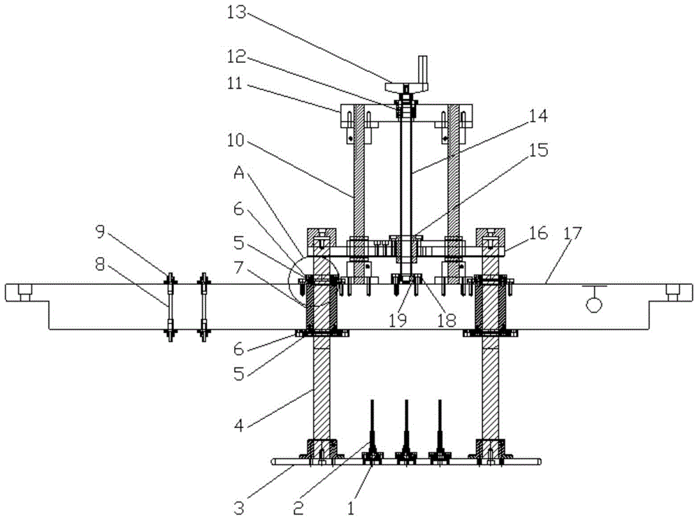
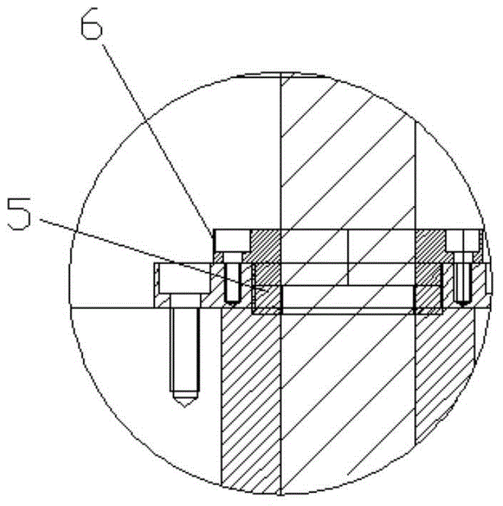
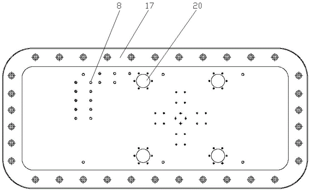
[0028] Such as figure 1 As shown in —3, the present invention includes a pulsating pressure measuring plate 3, a pulsating pressure sensor 2, a first guide rod 4, a water hole cover plate 17, a guide plate 16, a threaded rod 14, a threaded rod sleeve 15, a threaded rod seat 11 and a rocker Handle 13.

[0029] In this embodiment, four first guide rods 4 are provided, and corresponding positions on the water hole cover plate 17 are evenly distributed with four first guide holes 20 that are matched with the first guide rods 4. The first guide rods 4 The lower end is fixed on the upper surface of the pulsating pressure measuring plate 3, and the upper end passes through the first guide hole 20 and is fixedly connected to the upper guide plate 16; both the center of the threaded rod seat 11 and the guide plate 16 are provided with through holes, and the central through hol...


PUM


Abstract

The invention provides an asymmetric measuring device for propeller pulsating pressure and belongs to the field of ship hydrodynamics experiments. The asymmetric measuring device can efficiently acquire maximum propeller pulsating pressure when measuring pulsating pressure in a vacuole water tunnel, can realize continuous and quick adjusting of measuring state and is convenient to mount. The technical scheme includes that the asymmetric measuring device which is liftable comprises a pulsating pressure measuring flat plate, pulsating pressure sensors, first guide rods, a water tunnel cover plate, a guide plate, a threaded rod, a threaded rod sleeve, a threaded rod seat and a rocking handle.

Description

Technical field [0001] The invention relates to the field of ship hydrodynamic testing, in particular to an asymmetric measurement device for propeller pulsation pressure. Background technique [0002] Due to the rapid development of international trade, higher requirements have been placed on the shipping industry, container ships, ro-ro ships and other ship types have been widely used; the fleet has also developed into the ocean. The speed of this kind of civil ships continues to increase, resulting in a rapid increase in the power of a single engine, and the draft of the ship is restricted by the natural conditions and facilities of the harbor. The diameter of the propeller cannot be increased excessively, so the load of the propeller is heavier, and it is accompanied by the performance of the ship. Problems such as tail vibration, structural damage, noise and erosion have caused many countries to pay attention to the study of propeller excitation force. There are new develop...

Claims


Application Information

Patent Timeline
Patent Type & Authority Applications(China)
IPC IPC(8): G01M10/00
Inventor 熊鹰时立攀宋晗王波
Owner NAVAL UNIV OF ENG PLA
Learn More