
Rapid synchronous phasor correction method

A synchronized phasor and fast technology, which is applied in the direction of measuring devices, measuring electrical variables, and the phase angle between voltage and current, etc., can solve the problems of real-time measurement performance, phasor amplitude, angle accuracy reduction, and compensation failure. And other issues

Active Publication Date: 2015-02-25
NANJING GUODIAN NANZI POWER GRID AUTOMATION CO LTD
View PDF5 Cites 14 Cited by
  • Summary
  • Abstract
  • Description
  • Claims
  • Application Information

AI Technical Summary

Problems solved by technology

This kind of processing method has a heavy CPU load, and it cannot take into account the measurement performance and the real-time performance of phasor uploading, and the compensation formula derived from the theoretical formula is prone to division by 0, resulting in compensation failure.
The patent "A Method for Phasor Correction by a Synchronized Phasor Measuring Device" (200910087425.X) proposes a method of using function fitting to ensure the measurement accuracy of the amplitude and phase angle in the range of 45-55Hz. Filter processing, when the frequency offset is serious, the accuracy of the phasor amplitude and angle will be greatly reduced, and the error is related to the initial phase angle, making compensation difficult

Method used


Image

  • Rapid synchronous phasor correction method
  • Rapid synchronous phasor correction method
  • Rapid synchronous phasor correction method

Examples


Embodiment Construction

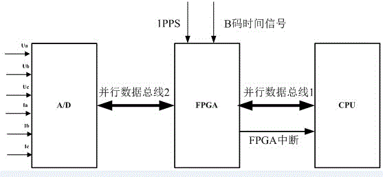
[0054] Attached below figure 1 And attached figure 2 , to further elaborate the technical content of the present invention. The following examples are only used to illustrate the technical solution of the present invention more clearly, but not to limit the protection scope of the present invention.

[0055] Such as figure 1 and figure 2, the present invention provides a kind of quick synchrophasor correction method, and this method comprises the following steps:

[0056] (1) FPGA and CPU are connected by 32-bit or 64-bit parallel bus 1 in hardware, FPGA has an interrupt signal connected to the external interrupt pin of CPU, FPGA is connected to 1PPS signal of standard clock and B code time signal, FPGA passes Parallel bus 2 controls the AD chip;

[0057] (2) Define the sampling configuration register (CONFIG_REG), sampling buffer register (DATA_REG), DFT coefficient original register (DFT_COEF), filter coefficient register (FIR_COEF), and DFT result buffer register (DF...


PUM


Abstract

The invention discloses a rapid synchronous phasor correction method which involves an initialization module, a synchronous sampling module, a phasor computation module, a phasor correction module, a phasor FIFO buffer area read-write interface module and a CPU compensation module. The rapid synchronous phasor correction method has the advantages that through the capacity of high-speed parallel computing of an FPGA, the data synchronous sampling process, recursive DFT operation and a phasor filter algorithm are finished in the FPGA, so that a CPU is released from frequent sampling interruption and the heavy DFT operation process, the main task is focused on response to commands of a master station, and communication instantaneity of a PMU is guaranteed. Meanwhile, the phasor filter algorithm is optimized through a DA algorithm, more-digit multiplication of long bytes can be carried out synchronously, and the computational speed is greatly improved.

Description

technical field [0001] The invention relates to a fast synchronous phasor correction method, which belongs to the technical field of electric power system automatic measurement. Background technique [0002] The synchronized phasor measurement unit (PMU) uses the satellite synchronous clock system to provide unified sampling pulse and standard time for synchronous sampling of the whole network in a wide area, so that each station has the same time reference point and sampling reference reference point , the synchrophasor obtained after synchronous sampling and calculation can accurately describe the dynamic process of the actual system, and provides a new data source for new protection, measurement and control, security and stability control of the power system. As an embedded device, the PMU device generally adopts fixed-interval sampling and fixed DFT coefficients, so that the data of the same time section in a wide area in different places can be obtained, and the amplitu...

Claims


Application Information

Patent Timeline
IPC IPC(8): G01R25/00
Inventor 温富光陈庆旭张守志
Owner NANJING GUODIAN NANZI POWER GRID AUTOMATION CO LTD
Learn More