An All Metal Laptop Antenna

A notebook computer, all-metal technology, applied in the directions of antenna support/installation device, radiating element structure, etc., can solve the problems of high return loss, large space occupation, low work efficiency, etc., to expand low-frequency bandwidth and reduce volume , the effect of reducing the space

Inactive Publication Date: 2017-03-29
SHANGHAI AMPHENOL AIRWAVE COMM ELECTRONICS CO LTD
View PDF14 Cites 0 Cited by
  • Summary
  • Abstract
  • Description
  • Claims
  • Application Information

AI Technical Summary

Problems solved by technology

[0005] The purpose of the present invention is to provide an all-metal notebook computer antenna to solve the problems of high return loss and low work efficiency in existing slot-type metal notebook computer antennas
[0006] The second purpose of the present invention is to provide an all-metal notebook computer antenna to solve the problem that the existing slot-type metal notebook computer antenna occupies a large space, which is not conducive to the thinner and thinner design of the notebook computer as a whole.

Method used


Image

  • An All Metal Laptop Antenna
  • An All Metal Laptop Antenna
  • An All Metal Laptop Antenna

Examples


Embodiment 1

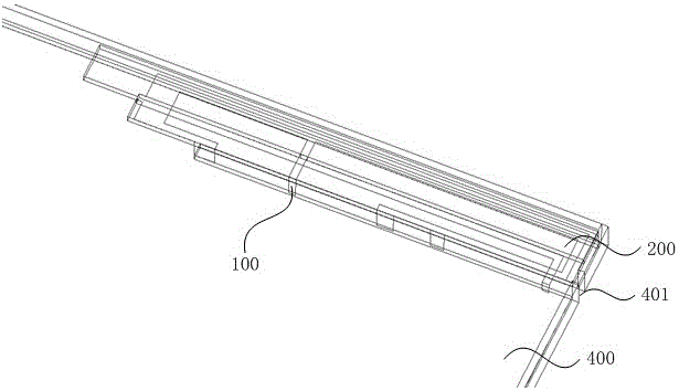
[0030] Such as figure 1 As shown, the antenna provided by the present invention includes an antenna body 100, a bracket 200 and an impedance matching circuit 300 ( figure 1 not shown in ), the all-metal notebook computer equipped with the antenna is provided with a linear slit 401 on the all-metal substrate 400, the slit 401 is parallel to and close to the upper edge of the all-metal substrate 400, and the bracket 200 is located on one side of the slit 401 and is parallel to the slit 401 . Wherein, the slit width is 2mm.

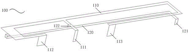
[0031] Such as figure 2 As shown, the antenna body 100 includes a first arm 110 and a second arm 120, the first arm 110 covers the upper surface of the bracket 200, the second arm 120 covers the lower surface of the bracket 200, the first end of the first arm 110 It is electrically connected with the first end of the second arm 120 . The first arm 110 includes a feeding point 111, a first grounding point 112, and a second grounding point 113. The feedin...

Embodiment 2

[0037] In this embodiment, except that the following contents are different from Embodiment 1, the rest of the technical features are the same as Embodiment 1, and will not be repeated here, only the differences are described as follows:

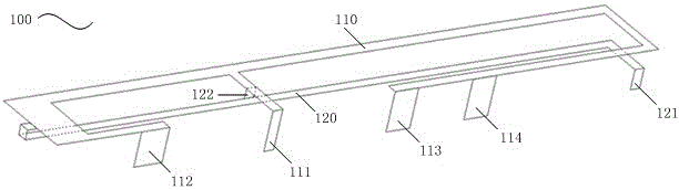
[0038] In this embodiment, the first arm 110 further includes a fourth ground point 114 , and the fourth ground point 114 is located between the second ground point 113 and the endpoint of the second end of the first arm 110 .

[0039] The fourth grounding point 114 can make the antenna of the present invention form a double resonant wave in the high frequency band 1710~2170MHz, which is used to widen the bandwidth of the high frequency band. By adjusting the position of the grounding point 114 left and right, the resonant frequency of the double resonant wave can be changed, so that Its return loss and efficiency completely cover 1710~2170MHz. The antenna body provided by Embodiment 2 is suitable for an environment in which the antenna cons...


PUM


Abstract

The invention provides an all-metal laptop antenna. The antenna comprises a bracket, an antenna body and an impedance matching circuit. As a kerf is formed in an all-metal substrate of an all-metal laptop, the antenna body is structurally divided into two parts which are arranged on the two sides of the bracket in a covering mode; in combination with the impedance matching circuit, a metal frame arranged above the kerf plays a role in radiating a low-frequency signal, and the antenna body plays a role in constructing a high-frequency resonance wave. The all-metal laptop antenna has better adaptability to the working environment of the antenna, is suitable for application in the situation that the antenna constraining environment is poor and can well meet the communication requirement of the all-metal ultra-thin laptop. The antenna of the gap-type metal laptop is low in return loss and high in working efficiency, and the space occupied by the antenna is effectively reduced; accordingly, the antenna provides favorable conditions for further miniaturization design of the metal laptop provided with the antenna structure.

Description

technical field [0001] The invention relates to a radio frequency antenna, in particular to an all-metal notebook computer antenna. Background technique [0002] With the continuous progress of society and the rapid development of science and technology, notebook computers have become an indispensable part of people's office life, and surfing the Internet is the main content of computer users. For portable notebook computers, the strong wireless signal Weakness is the key to the quality of Internet access. For the notebook computer itself, the ability to receive wireless signals is particularly important. [0003] However, the current notebook computers are gradually becoming thinner and more fashionable, leaving less and less space for antennas. At the same time, notebook computers have gradually supported 3G, 4G and other communication protocols from simply supporting WIFI and Bluetooth to achieve Internet access anytime, anywhere. call. In addition, in order to pursue d...

Claims


Application Information

Patent Timeline
Patent Type & Authority Patents(China)
IPC IPC(8): H01Q1/36H01Q1/22
Inventor 何大伟
Owner SHANGHAI AMPHENOL AIRWAVE COMM ELECTRONICS CO LTD
Why Eureka
Try Eureka