Eureka AIR delivers breakthrough ideas for toughest innovation challenges, trusted by R&D personnel around the world.

Tire power generation device

A technology for power generation devices and conductive devices, which is applied in the direction of generators/motors, electrical components, piezoelectric effect/electrostrictive or magnetostrictive motors, etc., and can solve the problems of small deformation of piezoelectric elements, low collected voltage, and To solve problems such as difficult methods, achieve the effect of reducing workload, reasonable structure and reducing energy consumption

Inactive Publication Date: 2015-02-25
DALIAN HUAGONG INNOVATION TECH
View PDF6 Cites 13 Cited by
  • Summary
  • Abstract
  • Description
  • Claims
  • Application Information

AI Technical Summary

Problems solved by technology

In order to reduce the consumption of petroleum resources and leave more non-renewable petroleum resources to future generations, people have carried out a lot of research and active exploration, among which there are many patents on tire power generation, but it will take a long time for the patented technology that can be actually applied the way to become a reality
The commonly used tire power generation technology is to use the energy generated by the deformation of the piezoelectric element to collect the energy, but the deformation of the piezoelectric element in the tire is small, the voltage generated is in the millivolt level, the collected voltage is low, and the power is small. The collection method is relatively difficult, and the energy collected is not enough to drive the car

Method used


Image

  • Tire power generation device
  • Tire power generation device
  • Tire power generation device

Examples


specific Embodiment approach 1

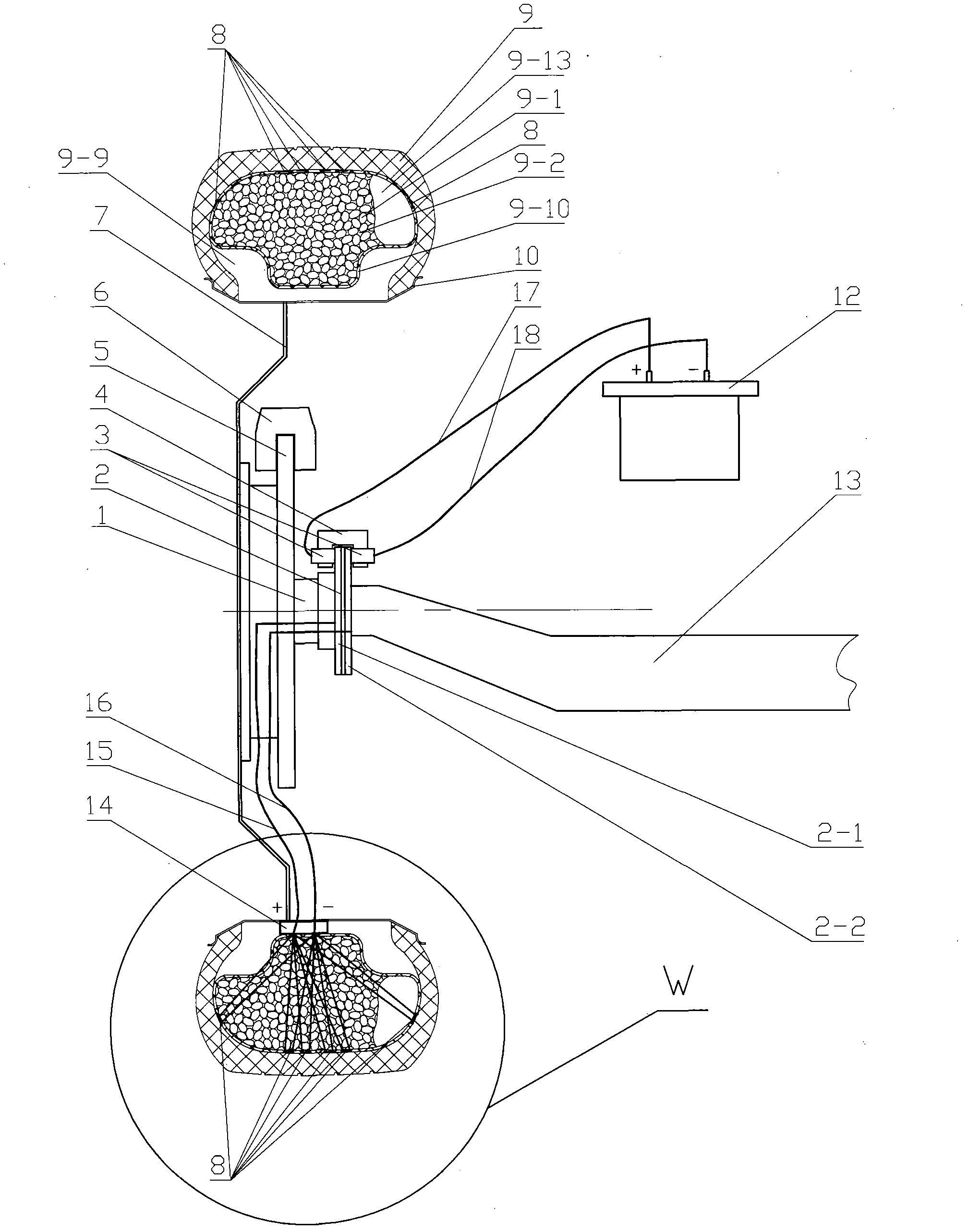
[0028] Specific implementation mode one: as figure 1 , 8 , 9, and 10, the tire power generation device includes a main shaft 1, a slip ring 2, a conductive device 4, a piezoelectric element 8, an outer tire 9, an elastic support body 9-13, an inner cavity 9-9, and a rubber tire 9 -10, rim 10, wire A15, wire B16, wire C17, wire D18, battery 12, vehicle frame 13 and electric energy converter 14.

[0029] The inside of the outer tire 9 is provided with a rubber tire 9-10, the cross section of the rubber tire 9-10 is a closed irregular ring, TPU is made into TPU foamed elastic particles 9-1, and the rubber tire 9-1 is put into the outer tire 9. Inside 10, countless TPU foamed elastic particles 9-1 are bonded together by adhesive or surface hot-melt technology, TPU foamed elastic particles 9-1 fill the space of rubber tire 9-10, TPU foamed elastic There are gaps 9-2 between the particles 9-1, and the gaps 9-2 are eliminated by pressurization or heating, or a small amount of gaps ...

specific Embodiment approach 2

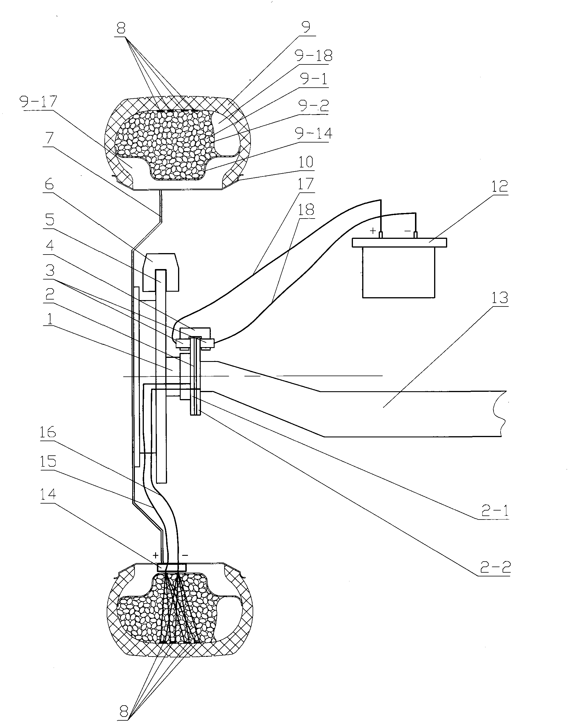
[0035] Specific implementation mode two: as figure 2 , 9 , 10, in this embodiment, the tire power generation device includes a main shaft 1, a slip ring 2, a conductive device 4, a piezoelectric element 8, an outer tire 9, an elastic support body A9-18, a rubber tire D9-14, Inner cavity G9-17, rim 10, lead A15, lead B16, lead C17, lead D18, accumulator 12, electric energy converter 14, rubber tire D9-14 and outer tire 9 are integrated with adhesive or hot-melt.

[0036] TPU is made into TPU foaming elastic particles 9-1, put into the inner part of the closed irregular ring formed by outer tire 9 and rubber tire D9-14, and countless TPU foaming elastic particles 9-1 are made of adhesive or surface heat It is bonded together by melting process, TPU foamed elastic particles 9-1 are filled with outer tire 9 and rubber tire D9-14 to form a closed irregular annular interior, and there are gaps between TPU foamed elastic particles 9-1 -2, TPU foamed elastic particles 9-1 are press...

specific Embodiment approach 3

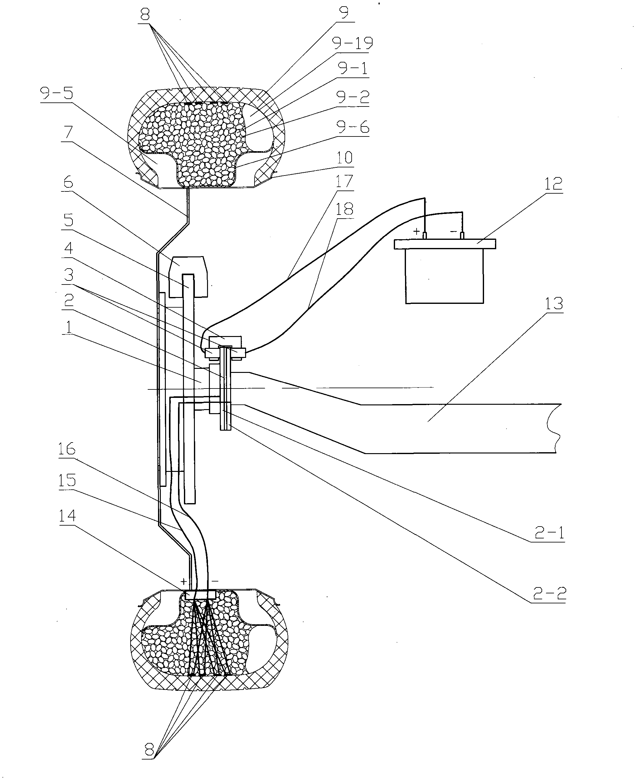
[0038] Specific implementation mode three: as image 3 , 9 , 10, in this embodiment, the tire power generation device includes a main shaft 1, a slip ring 2, a conductive device 4, a piezoelectric element 8, an outer tire 9, an elastic support body B9-19, a rubber tire B9-6, Inner chamber B9-5, rim 10, lead A15, lead B16, lead C17, lead D18, accumulator 12, electric energy converter 14, rubber tire B9-6 and outer tire 9 are integrated with adhesive or hot melt.

[0039] TPU is made into TPU foamed elastic particles 9-1, put into the closed ring-shaped interior of outer tire 9 and rubber tire B9-6, and countless TPU foamed elastic particles 9-1 are made of adhesive or surface hot-melt It is bonded together by the process, TPU foamed elastic particles 9-1 are filled in the closed ring surrounded by outer tire 9 and rubber tire B9-6, there are gaps 9-2 between TPU foamed elastic particles 9-1, TPU The foamed elastic particles 9-1 are pressurized or heated to eliminate the gap 9...


PUM


Abstract

The invention relates to a tire power generation device, in particular to a tire power generation device used for an automobile. The tire power generation device comprises a main shaft, a sliding ring, a conductive device, piezoelectric elements, an outer tire, an elastic supporting body, an inner cavity, a rubber tire, a storage battery and an electric energy converter. The rubber tire is arranged inside the outer tire, space of the rubber tire is filled with TPU foaming elastic particles, two or more piezoelectric elements are arranged at the cross-section portion of the outer tire, and two or more piezoelectric elements are arranged in the circumferential direction of the interior of the outer tire. The electric energy generated by connecting the piezoelectric elements in series or in parallel is transmitted into the electric energy converter to be transmitted into the storage battery, and the automobile is driven by the electric energy generated by the piezoelectric elements to travel, or the electric energy is supplied to automobile air conditioning, air circulating, lighting, music playing, charging and the like. The consumption of energy sources such as petroleum resources can be remarkably reduced, energy saving and emission reduction can be achieved, the environment can be protected, and the human can be facilitated.

Description

technical field [0001] The invention relates to a tire power generating device, in particular to an automobile tire power generating device. Background technique [0002] At present, the number of cars at home and abroad has exceeded 1.1 billion. With the improvement of people's living standards, the number of cars has also increased rapidly, and the energy consumption has also increased rapidly. Most of the cars are driven by gasoline and diesel engines. Refined from petroleum, petroleum is a non-renewable resource, petroleum resources are becoming less and less, resources are facing depletion, and human beings are becoming more and more dependent on petroleum. If the energy generated by the tires when the car is turning can be used, a lot of energy can be saved. Petroleum resources, reducing pollutant emissions, is conducive to protecting the environment, and its significance is immeasurable. In order to reduce the consumption of petroleum resources and leave more non-ren...

Claims


Application Information

Patent Timeline
IPC IPC(8): H02N2/18
Inventor 韩毅军时丕林刘桂红
Owner DALIAN HUAGONG INNOVATION TECH
Why Eureka
Eureka Blog
Learn More