Dual-Rail Precharge Logic Cell Architecture

A logic unit, pre-charging technology, applied in the direction of logic circuits with logic functions, etc., can solve the problem of small area cost and so on

Active Publication Date: 2017-08-04
山东天聚汇能微电子有限公司
View PDF5 Cites 0 Cited by
  • Summary
  • Abstract
  • Description
  • Claims
  • Application Information

AI Technical Summary

Problems solved by technology

[0004] The purpose of the present invention is to solve the problem of effectively solving the problem of early propagation effect in the case of small area expenditure, and provides a dual-rail pre-charging logic unit structure

Method used


Image

  • Dual-Rail Precharge Logic Cell Architecture
  • Dual-Rail Precharge Logic Cell Architecture
  • Dual-Rail Precharge Logic Cell Architecture

Examples


specific Embodiment approach 1

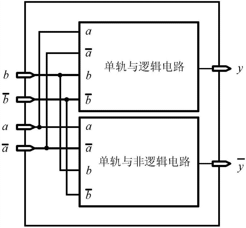
[0029] Specific implementation mode one: the following combination Figure 1 to Figure 3 Describe this embodiment mode, the dual-rail precharge logic unit structure described in this embodiment mode, it comprises monorail and logic circuit and monorail and non-logic circuit; Both monorail and logic circuit and monorail and non-logic circuit have four input ends, connect respectively Four input signals a, b and The output signal y of the single-rail AND logic circuit is the AND logic result of the input signals a and b; the output signal of the single-rail AND non-logic circuit is the AND logic result of input signals a and b;

[0030] input signal a, b and Both are 0, the logic unit is in the precharge state; the input signal a and are complementary signals, and b and When it is also a complementary signal, the logic unit is in the logic operation state;

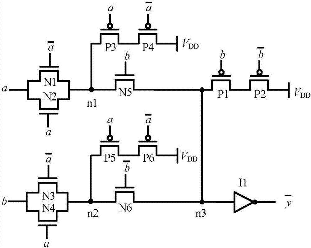
[0031] The single rail and logic circuit includes NMOS transistor N1', NMOS transistor N2', NMOS transistor ...

specific Embodiment approach 2

[0049] Specific implementation mode two: the following combination Figure 4 to Figure 6 Describe this embodiment mode, the dual-rail precharge logic unit structure described in this embodiment mode, it comprises monorail or logic circuit and monorail or non-logic circuit; Both monorail or logic circuit and monorail or non-logic circuit have four input ends, connect respectively Four input signals a, b and The output signal y of the single-rail OR logic circuit is the OR logic result of the input signals a and b; the output signal of the single-rail or non-logic circuit is the logical result of the OR of the input signals a and b;

[0050] input signal a, b and Both are 0, the logic unit is in the precharge state; the input signal a and are complementary signals, and b and When it is also a complementary signal, the logic unit is in the logic operation state;

[0051] The single-rail or logic circuit includes NMOS transistor N1', NMOS transistor N2', NMOS transis...


PUM


Abstract

The double-track precharge logic unit structure belongs to the field of circuit electronics. The invention aims to effectively solve the problem of early propagation effect under the condition of small area expenditure. The AND-NAND logic of the present invention comprises a monorail and logic circuit and a monorail and non-logic circuit; both circuits have four input terminals, respectively connected to four input signals a, b and the output signal y of the monorail and logic circuit as input signals The AND logic result of a and b; the output signal of the single-rail NOR logic circuit is the NAND logic result of the input signals a and b; OR-OR logic includes a single-rail OR logic circuit and a single-rail NOR logic circuit; both circuits have Four input terminals are respectively connected to four input signals a, b and the output signal y of the single-rail OR logic circuit is the OR logic result of the input signals a and b; the output signal of the single-rail OR non-logic circuit is the OR of the input signals a and b illogical result.

Description

technical field [0001] The invention relates to a logic unit structure, which is used to resist the differential power consumption analysis attack of a cryptographic chip, and belongs to the field of circuit electronics. Background technique [0002] Cryptography devices such as smart cards are widely used in various industry sectors such as telecommunications, finance, enterprise security and government, and the importance of security cannot be overstated. Although the embedded features of the cryptographic device make it impossible for attackers to directly access the key information in the cryptographic chip, the cryptographic chip will leak certain side channel information such as power consumption and electromagnetic radiation when it is working. Differential Power Analysis (DPA) ) attack technology uses the correlation between the key data and these information, and can analyze and obtain the value of the key through mathematical statistics and other methods. Due to t...

Claims


Application Information

Patent Timeline
Patent Type & Authority Patents(China)
IPC IPC(8): H03K19/20
Inventor 王晨旭王佰玲王新胜李杰罗敏宋晨晨逄晓赵雷鹏
Owner 山东天聚汇能微电子有限公司
Why Eureka
Try Eureka