Electrically driven rail vehicle

A rail vehicle and electric drive technology, which is applied in the direction of electric vehicles, motor vehicles, vehicle parts, etc., can solve the problems of insufficient optimization of driving operation, and achieve the effects of device saving and high detection accuracy

Inactive Publication Date: 2015-02-25
SIEMENS MOBILITY AUSTRIA GMBH
View PDF3 Cites 2 Cited by
  • Summary
  • Abstract
  • Description
  • Claims
  • Application Information

AI Technical Summary

Problems solved by technology

However, this is not enough for the optimization of the entire driving operation

Method used


Image

  • Electrically driven rail vehicle
  • Electrically driven rail vehicle
  • Electrically driven rail vehicle

Examples


Embodiment Construction

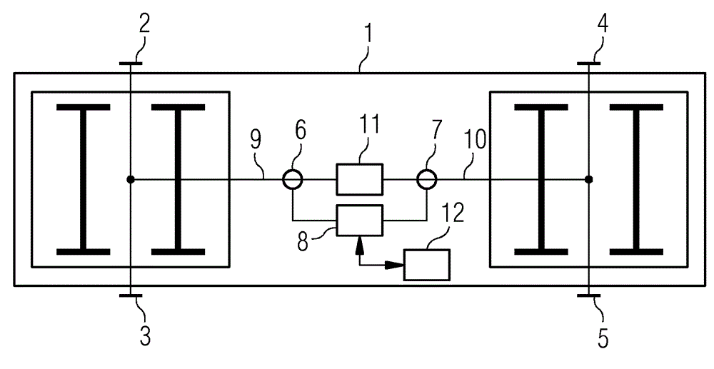
[0020] figure 1 An exemplary and schematic block diagram of an energy supply of an electrically driven rail vehicle is shown. The rail vehicle 1 has two bogies, each bogie having a current collector 2 , 3 , 4 , 5 arranged on both sides. The electrical lines to the current collectors 2 , 3 of the first bogie are interconnected within the area of ​​the first bogie and the electrical lines 9 lead from this connection point to the junction box 11 . The junction box 11 includes a bus bar at which all the leads are connected and from which the electrical consumers are supplied with electricity. The lines to the current collectors 4 , 5 of the second bogie are likewise connected to each other within the area of ​​the second bogie and the electrical lines 10 lead from this connection point to a junction box 11 . Arranged in the distribution of the lines 9 , 10 are current measuring devices 6 , 7 , which determine the current flowing in the lines 6 , 7 and transmit a signal proportio...


PUM


Abstract

The invention relates to an electrically driven rail vehicle (1) comprising at least one current collector (2, 3, 4, 5) arranged in the region of the chassis, and an electric line (9, 10) between the current collector (2, 3, 4, 5) and a junction box (11). A current measuring device (6, 7) is arranged in the course of the electric line (9, 10), which determines the current (i1, i2) flowing in the line (6, 7) and transmits a signal corresponding to the current strength (i1, i2) to an evaluation device (8).

Description

technical field [0001] The invention relates to an electrically driven rail vehicle. Background technique [0002] Short-distance rail vehicles, especially subways, are very often powered by current collectors arranged near the chassis of the vehicle, which are fed by means of elastic slides from busbars arranged next to the rails ("3. Tracks") receive energy. In these rail vehicles with current collectors in the area of ​​the vehicle chassis, a plurality of such collectors are very often provided, because on the one hand the electrical power is thus distributed and the individual collectors each necessarily transmit less power, and on the other hand Due to the generally interrupted busbars, several current consumption points need to be provided in order to be able to bridge these gaps so that the vehicle is powered over the entire road section. If a current collector is missing (for example broken or otherwise damaged), the vehicle can thus also be operated further. Here...

Claims


Application Information

Patent Timeline
Patent Type & Authority Applications(China)
IPC IPC(8): B60L9/00H02J4/00
CPCB60L2200/26H02J4/00B60L9/00B60L2240/429Y02T10/642B60L5/00B60L5/24Y02T10/64
Inventor E.贾科布森A.斯普伦格纳格H.斯泰宁格J.萨默尔
Owner SIEMENS MOBILITY AUSTRIA GMBH
Why Eureka
Try Eureka