Drill bit for deep and large hole drilling

A drill bit, deep and large technology, applied in the field of drill bits for deep and large hole drilling processing, can solve the problems of low cutting efficiency, easy chipping inserts, limited processing aperture and depth, etc., and achieve high cutting strength and easy chip removal. Effect

Inactive Publication Date: 2015-03-04
CHANGSHA XINGXIN MACHINERY EQUIP
View PDF5 Cites 4 Cited by
  • Summary
  • Abstract
  • Description
  • Claims
  • Application Information

AI Technical Summary

Problems solved by technology

[0009] In order to solve the above-mentioned problems such as the need for special machine tools for deep and large holes, low efficiency and high production cost for processing deep and large holes, easy chipping of blades, limitations in processing aperture and depth, and low cutting efficiency, the present invention aims to provide a special tool for deep and large holes. Large hole processing, deep and large hole processing drill bit with the characteristics of high drilling efficiency, strong support force during drilling, not easy to break the blade, and long service life of the drill bit

Method used


Image

  • Drill bit for deep and large hole drilling
  • Drill bit for deep and large hole drilling
  • Drill bit for deep and large hole drilling

Examples


Embodiment 1

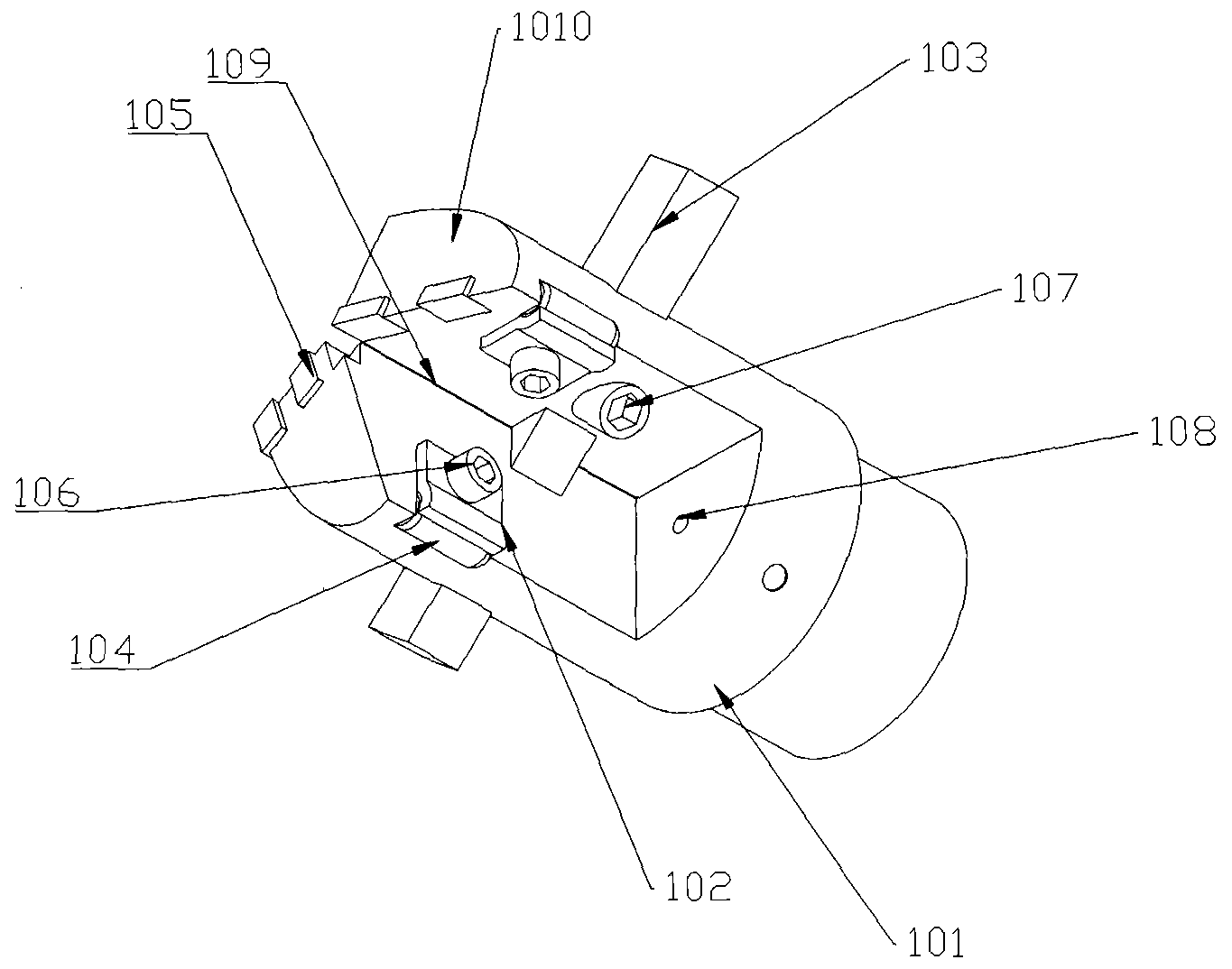
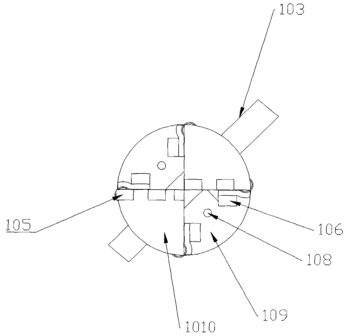
[0027] A drill bit for deep and large holes, such as figure 1 As shown, it includes a cutter head body 101, a roller pressing plate 102, a white steel blade 103, a support roller 104, a hard alloy blade 105, a roller pressing plate fixing screw 106, and a white steel knife fixing screw 107. The cutter head body is provided with a drilling chip removal area 109 in an X-shaped cross arrangement, and the drilling side surface 1010 on the cutter head body and the drilling chip removal area are symmetrically arranged on the cylinder where the cutter head body is located, and the drilling side surface 1010 Carbide blades 105 are cross-distributed on the cylindrical diameter position along the cutter head body, such as figure 2 shown. An arc hole for placing a cylindrical support roller 104 is machined on the axial side of the drilling chip removal area 109, and the support roller 104 is embedded in the arc hole, and the roller clamp 102 is fixed on the On the cutter head body, th...

Embodiment 2

[0029] A drill bit for deep and large holes, such as figure 1 As shown, it includes a cutter head body 101, a roller pressing plate 102, a white steel blade 103, a support roller 104, a hard alloy blade 105, a roller pressing plate fixing screw 106, and a white steel knife fixing screw 107. The cutter head body is provided with a drilling chip removal area 109 in an X-shaped cross arrangement, and the drilling side surface 1010 on the cutter head body and the drilling chip removal area are symmetrically arranged on the cylinder where the cutter head body is located, and the drilling side surface 1010 Carbide blades 105 are cross-distributed on the cylindrical diameter position along the cutter head body, such as figure 2shown. The circular arc holes for placing the cylindrical support rollers 104 are machined on the inner axial side of the drilling chip removal area 109, the support rollers 104 are embedded in the arc holes, and the roller clamp 102 is fixed by the roller cl...


PUM


Abstract

The invention belongs to the technical field of mechanical machining equipment, and particularly relates to a drill bit for deep and large hole drilling. The drill bit comprises a tool bit body, a roller pressing plate, a white steel knife strip, a supporting roller, a hard alloy blade, a roller pressing plate fixing screw and a white steel knife fixing screw. A drilling chip removal area which is arranged in an X crossing manner is machined on a drill bit body; a cutting liquid spraying hole is formed in the bottom of the drill bit body; and automatic chip removal in the machining process is achieved. The drill bit is special for deep and large hole machining and has the beneficial effects that the drilling efficiency is high, the supporting force in the drilling process is large, the blade is not prone to collapsing, and the service life of the drill bit is long.

Description

technical field [0001] The invention belongs to the technical field of mechanical processing equipment, relates to the technical field of processing deep and large holes on common machine tools, lathes or boring machines, and in particular relates to a drill bit used for drilling deep and large holes. Background technique [0002] In the processing of deep and large holes with a length-to-diameter ratio of L / a≥100, such as oil cylinders, stepped cylinders, etc., the surface finish and processing accuracy are required to be high, and it is completely complete processing with large processing allowances. The processing method has a large workload. At present, the commonly used deep hole processing drills include twist drills, gun drills, deep hole drills with chip removal in the wrong point BTA, ejector drills, and nesting drills. [0003] The rake angle of the twist drill has a large difference between the inside and the outside during processing. The rake angle of the main ...

Claims


Application Information

Patent Timeline
Patent Type & Authority Applications(China)
IPC IPC(8): B23B51/00B23B51/06
CPCB23B51/00B23B51/06
Inventor 吴雄光谢辉
Owner CHANGSHA XINGXIN MACHINERY EQUIP
Why Eureka
Try Eureka