Three-dimensional engraving machine
A three-dimensional engraving machine and column technology, applied in the field of engraving machines, can solve the problems of heavy overall quality of the upper part of the frame, poor practicability, and tool shaking, etc., and achieve the effect of improving the engraving quality, improving the engraving accuracy, and the tool running smoothly.
- Summary
- Abstract
- Description
- Claims
- Application Information
AI Technical Summary
Problems solved by technology
Method used
Image
Examples
Embodiment 1
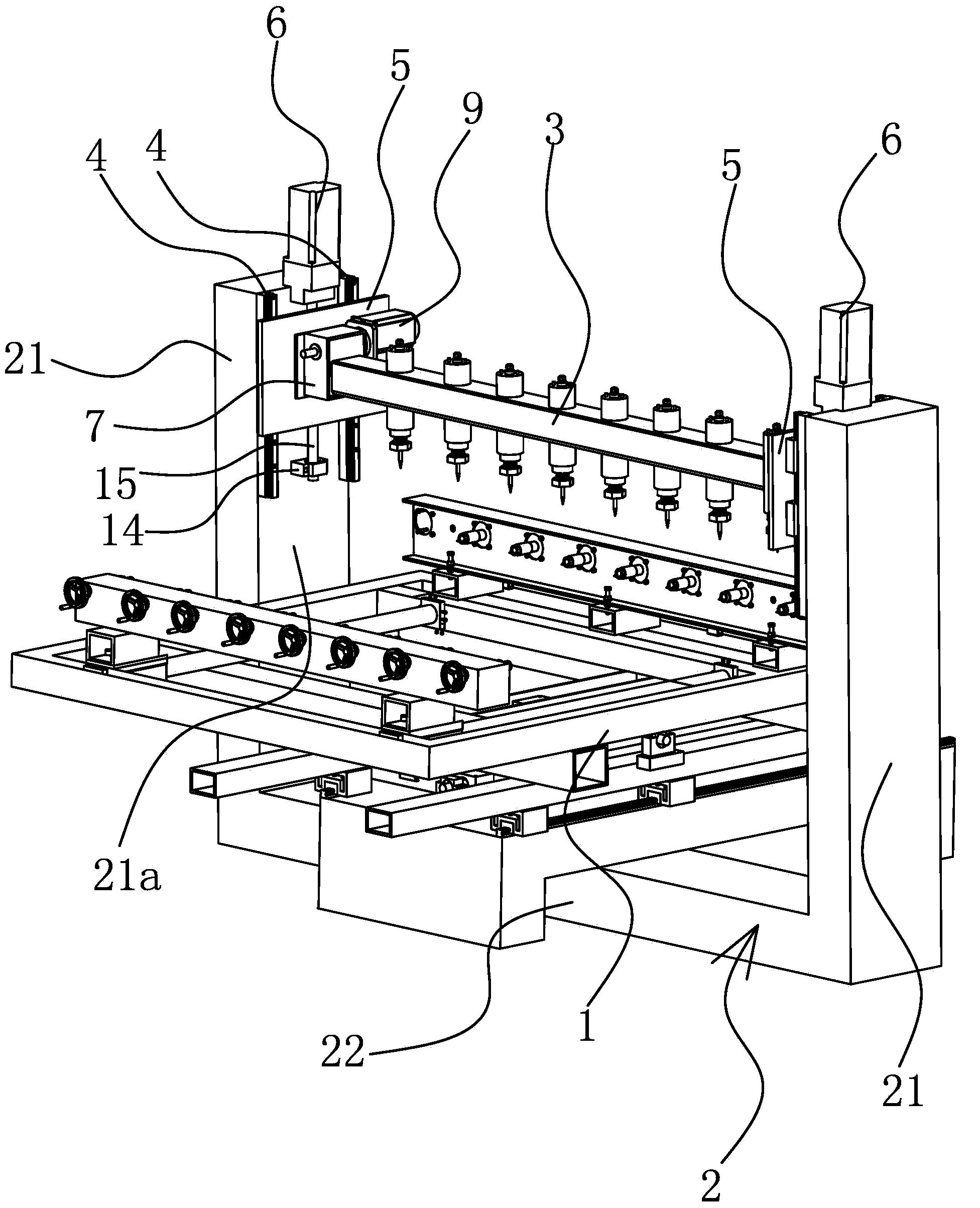
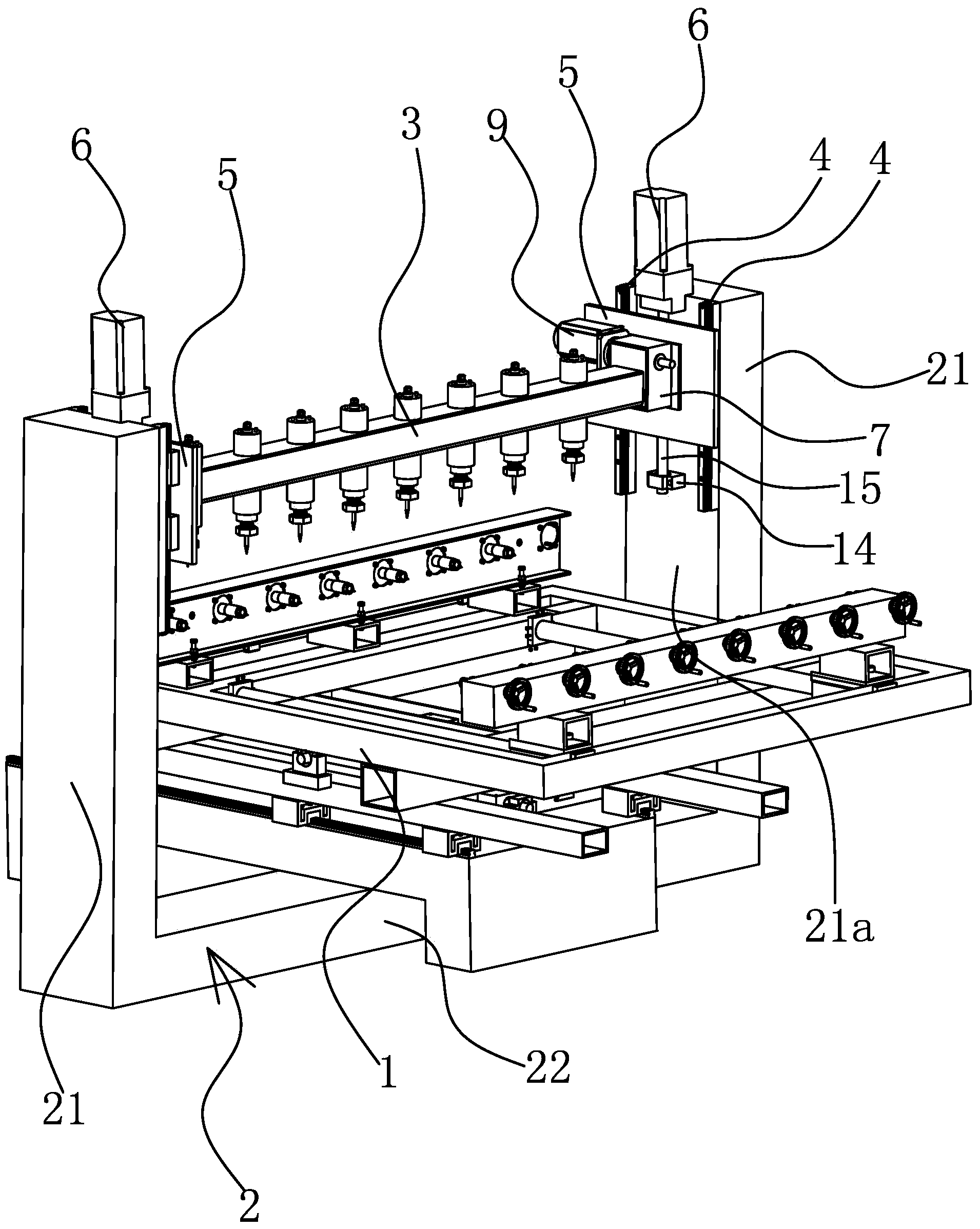
[0031] Such as figure 1 and figure 2 As shown, the three-dimensional engraving machine includes a frame 2 and a movable engraving platform 1 arranged on the frame 2, and a straight tool holder 3 for fixing the cutter is provided above the engraving platform 1, and the frame 2 includes a connection Beam 22 and two uprights 21, two uprights 21 are arranged vertically on both sides of engraving platform 1 respectively, two uprights 21 are flat quadrangular cylinders and parallel symmetrical arrangement, and the width of upright 21 inner side 21a is greater than The width of the front side of the column 21. The bottom ends of the two columns 21 are connected and fixed by the connecting beam 22, and the two columns 21, the tool holder 3 and the connecting beam 22 form a rectangular frame structure.
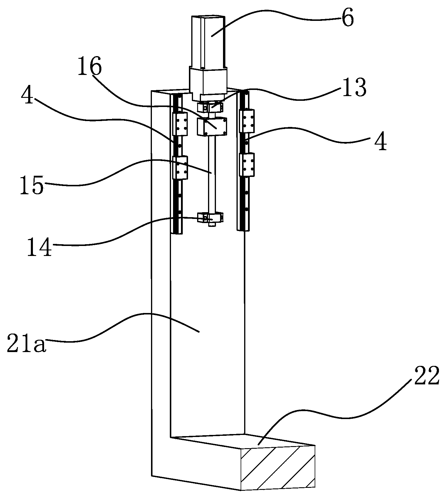
[0032] Such as image 3 As shown, the opposite sides of the two columns 21 are inner surfaces 21a, and vertically arranged guide rails 4 are respectively provided on the two inner ...
Embodiment 2
[0035] The structure and principle of this embodiment are basically the same as that of Embodiment 1, the difference is that: Figure 5 As shown, the frame 2 includes two uprights 21, connecting beams 22 and crossbeams 23, the connecting beams 22 and the crossbeams 23 are flat, the bottom ends of the two uprights 21 are connected and fixed by the connecting beams 22, and the upper ends of the two uprights 21 The beams 23 are connected and fixed, and the two columns 21, the beams 23 and the connecting beams 22 form a rectangular frame structure. Tool rest 3 is positioned at the place ahead of crossbeam 23, and guide rail 4 is positioned on the front side of two columns 21, and supporting plate 5 is made up of the first flat plate 51 that is parallel with front side and the second flat plate 52 that is perpendicular to first flat plate 51, and tool rest 3 is located between the second flat plates 52 and both ends of the tool holder 3 are vertically connected to the second flat p...
PUM
 Abstract
Description
Claims
Application Information
 - R&D
- Intellectual Property
- Life Sciences
- Materials
- Tech Scout
- Unparalleled Data Quality
- Higher Quality Content
- 60% Fewer Hallucinations
Browse by: Latest US Patents, China's latest patents, Technical Efficacy Thesaurus, Application Domain, Technology Topic, Popular Technical Reports.
© 2025 PatSnap. All rights reserved.Legal|Privacy policy|Modern Slavery Act Transparency Statement|Sitemap|About US| Contact US: help@patsnap.com


