Pneumatic centrifugal clutch and manufacturing method thereof

A centrifugal clutch and centrifugal body technology, applied in automatic clutches, mechanical drive clutches, clutches, etc., can solve the problems of poor transmission effect, high engine temperature, easy leakage, etc. stop smooth effect

Active Publication Date: 2015-03-04
LONGKOU HORIZON TRANSMISSION
View PDF13 Cites 5 Cited by
  • Summary
  • Abstract
  • Description
  • Claims
  • Application Information

AI Technical Summary

Problems solved by technology

Existing silicon oil fan clutch, after friction, the temperature rises and becomes thinner, then the viscosity decreases and the transmission effect becomes poor, and it is easy to leak and cause the engine temperature to be too high
The existing electromagnetic fan clutch has the disadvantage of relatively power consumption

Method used


Image

  • Pneumatic centrifugal clutch and manufacturing method thereof
  • Pneumatic centrifugal clutch and manufacturing method thereof
  • Pneumatic centrifugal clutch and manufacturing method thereof

Examples


Embodiment Construction

[0039] The first embodiment of the pneumatic centrifugal clutch of the present invention.

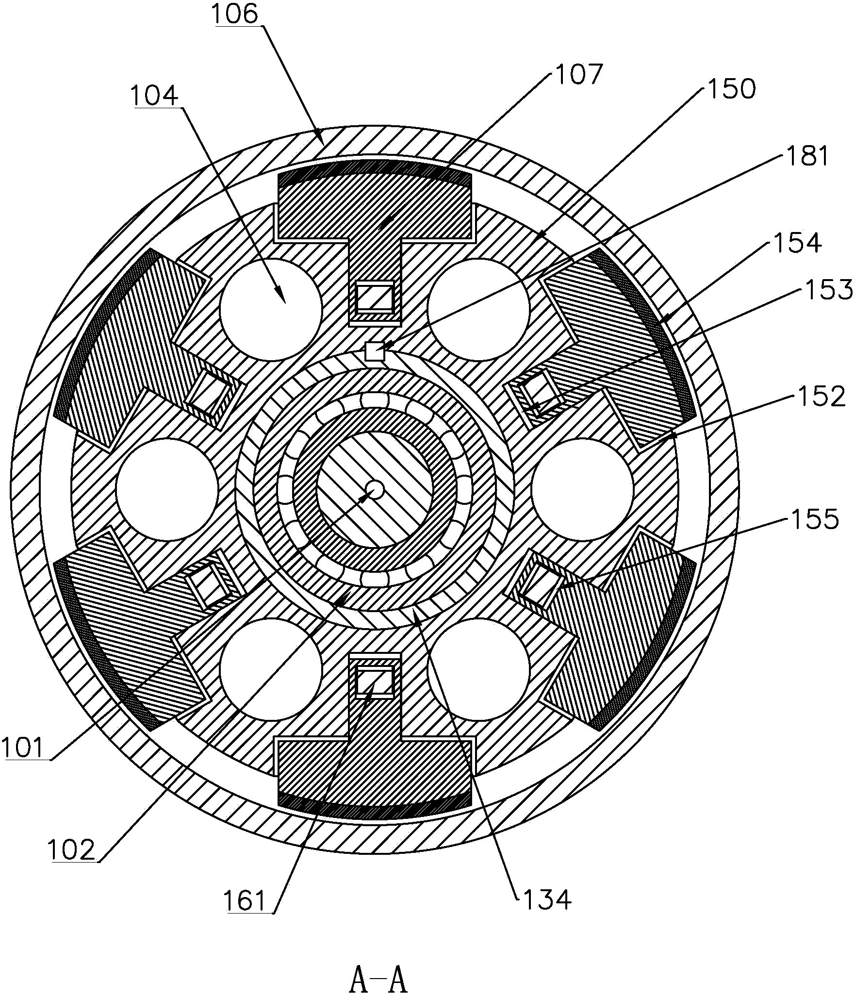
[0040] see figure 1 , figure 2 , which shows a first embodiment of the electromagnet core arrangement of the present invention.

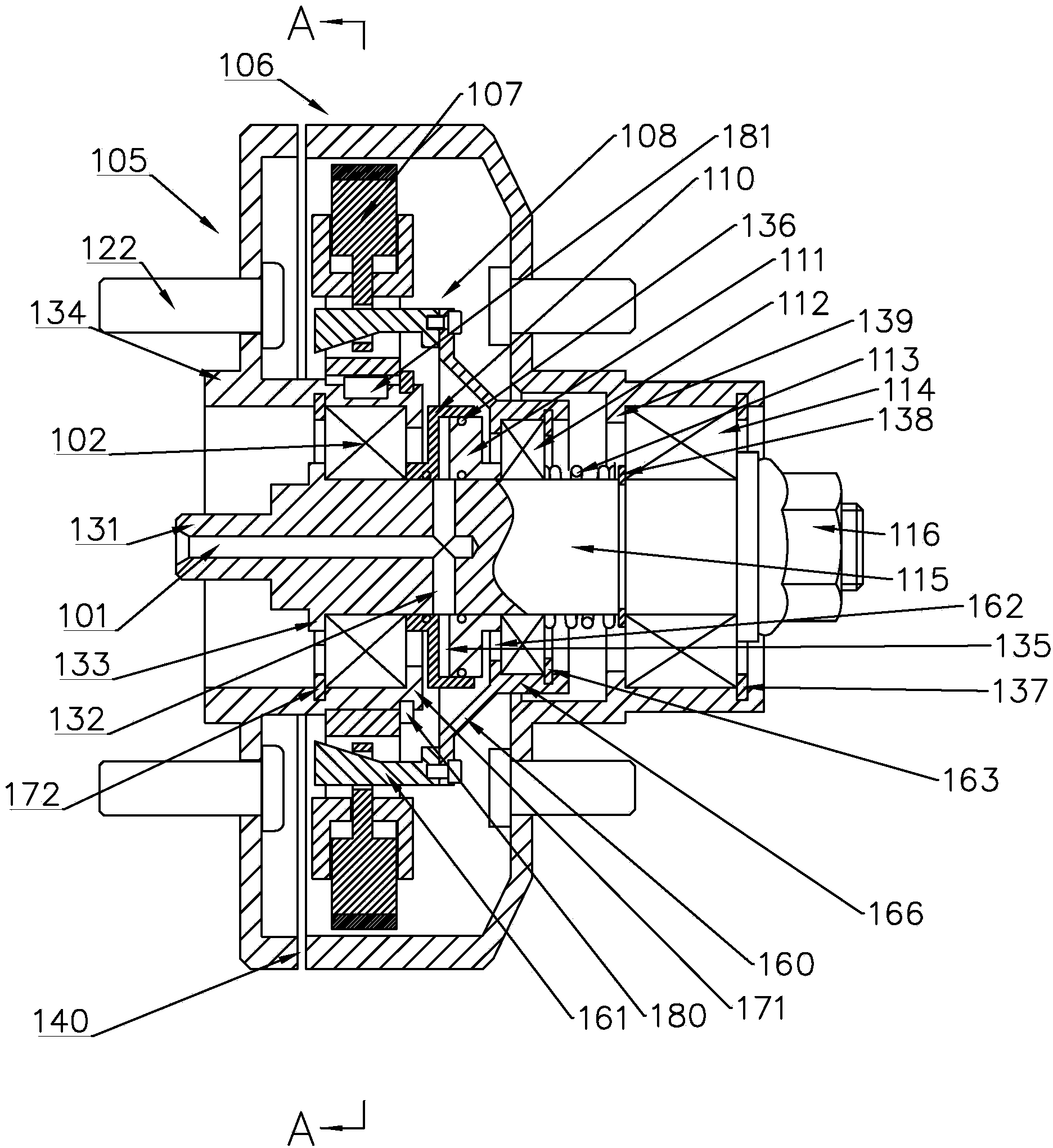
[0041] Such as Figure 1 As shown, the first embodiment of the present invention includes a main shaft 115, a driving part bearing 102, a driving part 105, a centrifugal body 107, a driven part 106, a circular cylinder 110, a piston 111, a thrust bearing 112, a return spring 113, a driven part Bearing 114, centrifugal body pulling mechanism 108. One end of the main shaft 115 forms a vent nozzle 131, and an air guide hole 101 is provided along the direction of the central axis from one end of the vent nozzle 131 of the main shaft 115. match. At the position near the blind end of the air guide hole 101 , six radial air guide holes 132 are opened in the radial direction, so as to guide the driving gas into the circular cylinder 110 . At the end of the mai...


PUM


Abstract

The invention discloses a pneumatic centrifugal clutch and a manufacturing method thereof and is aimed to provide a simple, durable and energy-saving clutch and a manufacturing method thereof. The clutch comprises a main shaft, a driving part, a driven part, a centrifugal body, and a centrifugal body drawing mechanism. A gas guide port is formed on the main shaft. One end of the gas guide port on the main shaft is open and extends into the main shaft along the axial direction of the main shaft. The gas guide port is communicated to the side wall of the main shaft along the radial direction of the main shaft and is communicated with a gas chamber formed between a cylinder and a piston sleeved on the main shaft. When a driving gas introduced into the gas guide port reaches the driving pressure, the piston drives the centrifugal body drawing mechanism so that the centrifugal body is separated from the driven part. When the driving gas introduced into the gas guide port is lower than the driving pressure, the drawing mechanism is reset, so that the centrifugal body contacts the driven part when the driving part rotates. The method comprises forming the gas guide port on the main shaft and arranging the centrifugal body and the drawing mechanism in the clutch to form the clutch. The method is used for manufacturing a fan clutch.

Description

technical field [0001] The present invention relates to a fan clutch for transmitting rotational motion and a manufacturing method, in particular to an aerodynamic centrifugal electromagnetic fan clutch and a manufacturing method. Background technique [0002] For the present invention, those skilled in the art can refer to the Chinese patent literature, the title of the invention is "forced separation centrifugal clutch", the publication number is "CN103089849A", the application number is 201310037862.7, and the application date is the patent text on January 31, 2013. This invention patent proposes to install a centrifugal body and a guide mechanism on the clutch, as well as a forced pulling mechanism that can make the centrifugal body radially inward, so as to realize the separation and engagement functions of the clutch. However, this invention patent has many deficiencies. For example, it only provides two specific approximate embodiments to realize the aforementioned a...

Claims


Application Information

Patent Timeline
Patent Type & Authority Applications(China)
IPC IPC(8): F16D43/18F16D23/12
Inventor 王兆宇邢子义
Owner LONGKOU HORIZON TRANSMISSION
Why Eureka
Try Eureka