A Three-Stage Interlocking Braking System for a Tire Roller

A technology for tire rollers and braking systems, which is applied to hydraulic brake transmissions, motor vehicles, safety devices of power plant control mechanisms, etc., can solve the problems of rapid brake pad wear, reduced braking performance, and large mass inertial force. , to achieve reliable braking performance, protection from premature wear, and good operating comfort.

Active Publication Date: 2015-12-30
柳工无锡路面机械有限公司
View PDF4 Cites 0 Cited by
  • Summary
  • Abstract
  • Description
  • Claims
  • Application Information

AI Technical Summary

Problems solved by technology

In the existing two-stage braking system, the driving system only brakes the wheel side alone, or only relies on the self-locking braking of the hydraulic system when there is no flow output from the hydraulic system. However, due to the high speed and mass inertia of the tire roller The large force makes the impact generated when braking is large, the reliability of braking performance is poor, and the brake pads wear quickly, etc. At the same time, the impact when the roller starts and stops may affect the quality of road compaction
[0005] The braking system of mechanically driven tire rollers still has the disadvantages of insufficient air pressure after continuous braking (such as continuous braking on slopes), the braking performance of the whole machine will decrease, the failure rate of braking components is high, and the brake pads on the wheel wear quickly. The high-speed tire roller has a great impact on the hydraulic system when braking at high speed. The braking condition caused by inertial force will cause the hydraulic system to back-drag the engine, causing the engine to overspeed and affecting the service life of the engine.

Method used


Image

  • A Three-Stage Interlocking Braking System for a Tire Roller
  • A Three-Stage Interlocking Braking System for a Tire Roller

Examples


Embodiment Construction

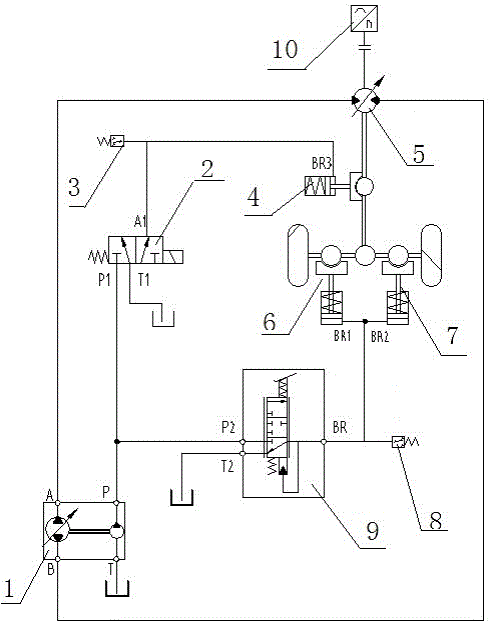
[0033] see figure 1 and figure 2 , the present invention relates to a three-stage interlocking brake system of a tire roller, which are: the handle returns to the middle hydraulic neutral position self-locking brake (hand brake), rear wheel edge brake (pedal brake), rear axle Brakes (parking and emergency braking).

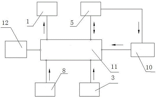
[0034] It includes travel pump 1, emergency brake solenoid valve 2, emergency brake pressure switch 3, drive axle brake 4, drive motor 5, first wheel brake 6, second wheel brake 7, foot brake pressure transmitter 8. Foot brake valve 9, drive motor speed sensor 10, controller 11 and handle 12.

[0035] Port A (first high-pressure oil outlet) and port B (second high-pressure oil outlet) of walking pump 1 are connected to the inlet and outlet of drive motor 5 to form a closed system. Port P of walking pump 1 (charge pump outlet) is connected with the P1 port (oil inlet port) of the emergency brake solenoid valve 2 and the P2 port (oil inlet port) of the foot brak...


PUM


Abstract

The invention relates to a three-level interlocking brake system of a pneumatic tyre roller. The three-level interlocking brake system is characterized by including hydraulic center self-locking brake, wheel-side brake and rear axle brake and consisting of a travel pump (1), an emergency brake solenoid valve (2), a drive axle brake (4), a drive motor (5), a first wheel-side brake (6), a second wheel-side brake (7), a foot brake pressure transmitter (8), a foot brake valve (9), a drive motor revolution sensor (10), a controller (11) and a handle (12). As interlocking linkage protection and power cut-off protection to hand brake, foot brake and emergency brake are realized by means of the electronic control technology and the sensor technology, reliability, stability and operational comfort of the brake performance of the whole unit are improved, and road surface operation quality is improved.

Description

technical field [0001] The invention relates to a three-stage interlocking braking system for hydraulically driven tire rollers. Background technique [0002] At present, tire rollers generally have two main transmission modes: hydraulic drive and mechanical drive, and the corresponding braking systems are mainly as follows: The braking system of mechanically driven tire rollers uses the rear axle brake as the service brake, and the rear wheel wheel brake As a parking brake, an air cap oil system is generally used. [0003] The brake system of the hydraulically driven tire roller generally controls the hydraulic pump swash plate to return to the central closed system hydraulic self-locking for service braking, and the brake of the reducer or drive axle is used as the parking brake. [0004] These two mainstream braking systems are two-stage braking systems, that is, only two-stage braking systems for service braking and parking are used. In the existing two-stage braking s...

Claims


Application Information

Patent Timeline
Patent Type & Authority Patents(China)
IPC IPC(8): B60T7/04B60T11/10B60K28/00
Inventor 宋鹏飞程观润孙甜甜谢兴友卢洪
Owner 柳工无锡路面机械有限公司
Why Eureka
Try Eureka