Mechanical sealing device for magnetofluid lubricating and adaptive sealing control method
A mechanical sealing device, sealing device technology, applied in the direction of engine sealing, mechanical equipment, engine components, etc.
- Summary
- Abstract
- Description
- Claims
- Application Information
AI Technical Summary
Problems solved by technology
Method used
Image
Examples
Embodiment 1
[0084] 1. The structure of ferrofluid lubricated non-contact mechanical seal
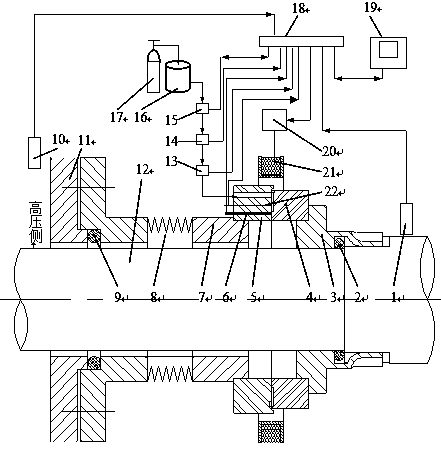
[0085] The structure of the magnetic fluid lubricated mechanical seal device of the present invention is as attached figure 1 shown.
[0086]The magnetohydrodynamic lubrication mechanical seal device of the present invention includes a programmable controller 18, a rotating shaft 12, a sealing chamber 11 installed on the rotating shaft 12, a moving ring seat 3 and a static ring seat 7, and the sealing chamber 11 Set on one side of the rotating shaft 12, the outside of the sealed cavity 11 is provided with a static ring seat 7 and a moving ring seat 3, a static ring 5 is installed on the static ring seat 7, a moving ring 4 is installed on the moving ring seat 3, and a moving ring 4 Cooperate with one end face of static ring 5.
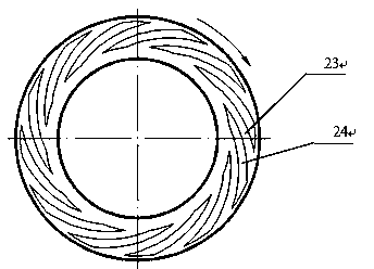
[0087] An axial drainage hole is arranged in the static ring 5, and one end of the drainage hole is led to the mating end faces of the dynamic and static rings, and the ot...
Embodiment 2
[0110] Self-adaptive sealing control method of the present invention
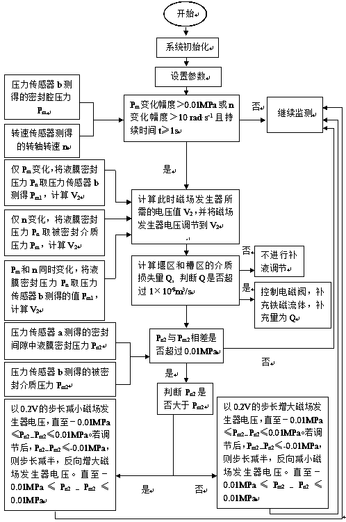
[0111] When the mechanical seal is in normal working condition, the pressure of the liquid film seal is equivalent to the pressure of the sealed medium, so that the sealed medium will not leak from the end faces of the sealing ring. Due to changes in operating parameters (pressure of the sealed medium and rotational speed of the rotating shaft), the pressure of the liquid film seal is not equal to the pressure of the sealed medium. At this time, the mechanical seal cannot maintain normal working condition.
[0112] Ferrofluid viscosity changes with changes in magnetic field strength. When the magnetic field strength increases, the viscosity of the ferrofluid increases correspondingly, and vice versa, the viscosity of the ferrofluid decreases. When the viscosity of the ferrofluid increases, the pressure of the fluid film increases; otherwise, the pressure of the ferrofluid film decreases. According to thi...
Embodiment 3
[0161] Step 1, start the program and set parameters;
[0162] 1 Turn on the computer and start the program.
[0163] 2 Manual control, turn on the equipment operation switch. The switch of the electromagnetic valve is manually controlled by the computer, so that a stable ferrofluid liquid film is generated in the sealing ring, so that the sealing structure is in a normal operating state.
[0164] 3Set the parameters.
[0165] The parameters set include:
[0166] ① Input the resistance R of the copper wire in the magnetic field generator = 0.02176Ω, and the proportional coefficient K = 18638 between the magnetic field strength in the sealed gap and the current in the magnetic field generator coil.
[0167] ②Input ferrofluid carrier fluid viscosity η c =1.1×10 -3 Pa·s (with kerosene as the base fluid), the average length of the dispersant chain molecules in the ferrofluid δ=8.6×10 -9 m, the radius r of the solid-phase magnetic particle p =5×10 -9 m, the mass component of...
PUM
| Property | Measurement | Unit |
|---|---|---|
| Viscosity | aaaaa | aaaaa |
| Average length | aaaaa | aaaaa |
| Radius | aaaaa | aaaaa |
Abstract
Description
Claims
Application Information
 - R&D
- Intellectual Property
- Life Sciences
- Materials
- Tech Scout
- Unparalleled Data Quality
- Higher Quality Content
- 60% Fewer Hallucinations
Browse by: Latest US Patents, China's latest patents, Technical Efficacy Thesaurus, Application Domain, Technology Topic, Popular Technical Reports.
© 2025 PatSnap. All rights reserved.Legal|Privacy policy|Modern Slavery Act Transparency Statement|Sitemap|About US| Contact US: help@patsnap.com


